13-18-609 Page 53
5-7
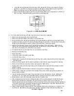
Figure 5- 4 – PRESSURE DEW POINT OF COMPRESSED AIR
OIL SEPARATION RESERVOIR
/
COALESCING ELEMENT
- This device serves multiple functions in
the compressor package:
·
Air/oil centrifugal separation
- The bulk of the liquid oil is separated, by change of direction,
impingement and additional centrifugal effects, away from the compressed air and aerosol streams,
and is then gravity-collected at the bottom of the sump.
·
Oil degassing and holding
- The sump has sufficient holding capacity to degas the oil mass before
it is drained off on its way to cooling, filtering and re-injection. It also serves as a storage volume for
the oil mass migrating from higher elevations (e.g., oil cooler, compressor casings, and piping).
·
Air/oil final separation
- The aerosols and compressed air streams are led to the upper portion of
the sump, where the coalescing element resides. The fine droplets of oil (aerosol) are trapped in the
element media, coalesced, then gravity-drained, through a low-point connection and associated
tubing (oil return line) into a lower pressure region of the compressor.
Separation performance -
The package oil separation system has been designed to yield 2 ppm total oil
carryover at the discharge of the air/oil reservoir
– the oil content level at the discharge of the package will
be lower and will depend on the amount of moisture rejected by the aftercooler.
This high level of performance will be affected by the following typical offset conditions:
·
Contaminated (e.g., dirt, varnish, moisture) or damaged (e.g., ruptured) coalescing element.
·
Contaminated (e.g., dirt, varnish, moisture) or inadequate oil in use.
·
High oil level in air/oil reservoir.
·
Blockage of oil return line strainer or orifice.
·
Abnormally frequent or fast depressurization cycles - leading to oil foaming.
80
90
100
110
120
130
140
150
160
170
180
190
200
210
220
230
240
250
260
30
40
50
60
70
80
90
100
110
120
130
Discharge PDP
-°
F
Ambient Temp - °F
Pressure Dew Point Trend
100psig
125psig
150psig
175psig
Summary of Contents for VS80A
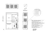
Page 33: ...13 18 609 Page 32 4 7 300CGE546 04 Ref Drawing Page 2 of 4...
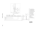
Page 34: ...13 18 609 Page 33 4 8 300CGE546 04 Ref Drawing Page 3 of 4...
Page 35: ...13 18 609 Page 34 4 9 300CGE546 04 Ref Drawing Page 4 of 4...
Page 37: ...13 18 609 Page 36 4 11 301CGE546 B Ref Drawing Page 2 of 4...
Page 38: ...13 18 609 Page 37 4 12 301CGE546 B Ref Drawing Page 3 of 4...
Page 39: ...13 18 609 Page 38 4 13 301CGE546 B Ref Drawing Page 4 of 4...
Page 41: ...13 18 609 Page 40 4 15 302CGE546 05 Ref Drawing Page 2 of 4...
Page 42: ...13 18 609 Page 41 4 16 302CGE546 05 Ref Drawing Page 3 of 4...
Page 43: ...13 18 609 Page 42 4 17 302CGE546 05 Ref Drawing Page 4 of 4...
Page 45: ...13 18 609 Page 44 4 19 303CGE546 B Ref Drawing Page 2 of 4...
Page 46: ...13 18 609 Page 45 4 20 303CGE546 B Ref Drawing Page 3 of 4...
Page 47: ...13 18 609 Page 46 4 21 303CGE546 B Ref Drawing Page 4 of 4...
Page 70: ...13 18 609 Page 69 9 2 Figure 9 1 MINIMUM DISCHARGE PRESSURE CHECK VALVE...
Page 86: ...NOTES...
Page 87: ...NOTES...


