14
-4
13
-18
-610 Page
79
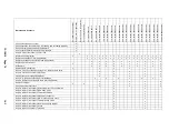
Maintenance Schedule
As indicated by Controller
Every 8 hours of operation
Every 125 hours of operation
Per oil analysis results
63 months/21000hours
66 months/22000hours
69 months/23000hours
72 months/24000hours
75
months/25000hours
78 months/26000 hours
81 months/27000 hours
84 months/28000hours
87 months/29000hours
90 months/30000hours
93 months/31000hours
96 months/32000hours
99 months/33000hours
102 months/34000hours
105 months/35000hours
108 months/36000hours
111 months/37000hours
114 months/38000 hours
117 months/39000 hours
120 months/42000hours
Check air/oil reservoir oil level
x
Check operation of the machine, is it loading and unloading properly
x
Check discharge pressure and temperature
x
Check control panel for advisory text messages
x
Inspect, Clean if necessary Cooler / Fan
x
Replace oil filter element
x
x
x
x
x
x
x
x
x
x
x
x
x
x
x
x
x
x
x
x
Control Box Filter (if applicable)
x
x
x
x
x
x
x
x
x
x
x
x
x
x
x
x
x
x
x
x
Replace cool air inlet filter pad (if applicable)
x
x
x
x
x
x
x
x
x
x
Replace air filter element
x
x
x
x
x
x
x
x
x
x
Oil Sample
x
x
x
x
x
x
x
x
x
x
Replace Air/Oil Separator
x
x
x
x
x
Inspect, clean if necessary scavenge line, replace check valve
x
x
x
x
x
Inspect, service if necessary Inlet Valve
x
x
x
x
x
Visually check for leakage Shaft Seal
x
x
x
x
x
Inspect, re-grease if necessary Motor Bearings
x
x
x
x
x
x
x
Inspect, Replace if necessary Drive Belts (if applicable)
x
x
x
x
x
Replace Lubricant
x
x
x
x
x
x
x
Check pressure relief valve
x
x
x
x
x
Inspect, replace if necessary Solenoid Valves / Vacuum Switch
x
x
x
Inspect, replace if necessary Blow-down Valve
x
x
x
Inspect, replace if necessary Thermistor Probes
x
x
x
Inspect, replace if necessary Pressure Transducer
x
x
x
Inspect, replace if necessary Min. Pressure/Check Valve
x
x
x
Inspect, replace if necessary Thermal Mixing Valve
x
x
x
Inspect, replace if necessary the drive Coupling Spider
x
x
x
Inspect, replace if necessary Hoses
x
x
x
Inspect, repair if necessary Turn valve
x
x
x
Summary of Contents for VS80A
Page 33: ...13 18 609 Page 32 4 7 300CGE546 04 Ref Drawing Page 2 of 4...
Page 34: ...13 18 609 Page 33 4 8 300CGE546 04 Ref Drawing Page 3 of 4...
Page 35: ...13 18 609 Page 34 4 9 300CGE546 04 Ref Drawing Page 4 of 4...
Page 37: ...13 18 609 Page 36 4 11 301CGE546 B Ref Drawing Page 2 of 4...
Page 38: ...13 18 609 Page 37 4 12 301CGE546 B Ref Drawing Page 3 of 4...
Page 39: ...13 18 609 Page 38 4 13 301CGE546 B Ref Drawing Page 4 of 4...
Page 41: ...13 18 609 Page 40 4 15 302CGE546 05 Ref Drawing Page 2 of 4...
Page 42: ...13 18 609 Page 41 4 16 302CGE546 05 Ref Drawing Page 3 of 4...
Page 43: ...13 18 609 Page 42 4 17 302CGE546 05 Ref Drawing Page 4 of 4...
Page 45: ...13 18 609 Page 44 4 19 303CGE546 B Ref Drawing Page 2 of 4...
Page 46: ...13 18 609 Page 45 4 20 303CGE546 B Ref Drawing Page 3 of 4...
Page 47: ...13 18 609 Page 46 4 21 303CGE546 B Ref Drawing Page 4 of 4...
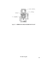
Page 70: ...13 18 609 Page 69 9 2 Figure 9 1 MINIMUM DISCHARGE PRESSURE CHECK VALVE...
Page 86: ...NOTES...
Page 87: ...NOTES...

