13-18-609 Page 83
15-4
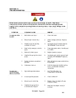
SYMPTOM
POSSIBLE CAUSE
REMEDY
Excessive oil at
intake filter area
1.
Intake valve seals leaking.
1.
Check location ventilation and
improve if necessary. Inspect, repair
or replace valve.
2.
Slow intake valve poppet
action
2.
Inspect poppet and guide surfaces.
Replace if necessary.
3.
Feed 3-way solenoid valve
malfunction
3.
Repair, clean or replace valve.
Oil carryover
1.
Overfilling oil separation
vessel
1.
Drain excess oil from system.
2.
Clogged oil return line orifice
2.
Inspect and service.
3.
Clogged oil return line strainer
3.
Inspect and service.
4.
Clogged, broken, or loose oil
return line fittings
4.
Inspect and tighten or replace.
5.
Ruptured oil separator
element.
5.
Replace element.
6.
Loose assembly
6.
Tighten all fittings and gaskets.
7.
Foam caused by use of
incorrect oil
7.
Use Gardner Denver AEON 9000SP
oil only.
8.
Minimum pressure valve
malfunction
– discharge
pressure below 80 psig
8.
Repair or replace. Inspect, adjust or
replace regulator.
Low Discharge
Temperature
1.
Oil mixing valve stuck on full
cooler flow mode
1.
Check 24 Vdc power feed to servo.
Check ModBus connection to servo.
Check servo-to-valve coupling.
Check rotation of ball valve.
2.
Short load/unload cycles do
not allow oil to reach normal
operating temperature
2.
Adjust
“Auto Timer” in AirSmart
controller to at least 5 min value.
This action forces package to
operate at min speed for set time
before stopping.
Summary of Contents for VS80A
Page 33: ...13 18 609 Page 32 4 7 300CGE546 04 Ref Drawing Page 2 of 4...
Page 34: ...13 18 609 Page 33 4 8 300CGE546 04 Ref Drawing Page 3 of 4...
Page 35: ...13 18 609 Page 34 4 9 300CGE546 04 Ref Drawing Page 4 of 4...
Page 37: ...13 18 609 Page 36 4 11 301CGE546 B Ref Drawing Page 2 of 4...
Page 38: ...13 18 609 Page 37 4 12 301CGE546 B Ref Drawing Page 3 of 4...
Page 39: ...13 18 609 Page 38 4 13 301CGE546 B Ref Drawing Page 4 of 4...
Page 41: ...13 18 609 Page 40 4 15 302CGE546 05 Ref Drawing Page 2 of 4...
Page 42: ...13 18 609 Page 41 4 16 302CGE546 05 Ref Drawing Page 3 of 4...
Page 43: ...13 18 609 Page 42 4 17 302CGE546 05 Ref Drawing Page 4 of 4...
Page 45: ...13 18 609 Page 44 4 19 303CGE546 B Ref Drawing Page 2 of 4...
Page 46: ...13 18 609 Page 45 4 20 303CGE546 B Ref Drawing Page 3 of 4...
Page 47: ...13 18 609 Page 46 4 21 303CGE546 B Ref Drawing Page 4 of 4...
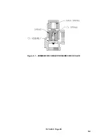
Page 70: ...13 18 609 Page 69 9 2 Figure 9 1 MINIMUM DISCHARGE PRESSURE CHECK VALVE...
Page 86: ...NOTES...
Page 87: ...NOTES...

