
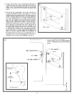
4. Drill 4 holes 17/32” diameter through transom. Make sure
drill bit is held perpendicular to the transom when drilling.
Drill one hole, 3/8” diameter in a suitable area between
the four 17/32” diameter holes to route electrical wires
from the actuator to the battery. (See Fig. 4)
5. Lay backing plates over mounting flanges so there is 1/2”
or more of overhang on all 4 sides. Mark 2 holes on each
backing plate and through drill 17/32” diameter. Make
sure holes are drilled perpendicular to surface.
6. Attach the Motor Bracket to the transom after coating the
inside surfaces of the mounting flanges and backing plates
with a marine adhesive/sealant compound. Apply a small
amount in each hole on both sides of the transom. Secure
in place with supplied hardware. Insert cable from
hydraulic actuator through 3/8” diameter hole in transom.
Allow enough slack for operation of actuator and caulk
cable in hole with marine grade silicone. (See Fig. 3)
FIG. 4
7.
Electrical
Select a suitable place on the cockpit coaming to
attach the activation switch. It is recommended that the
switch be located in an area that allows a visual sight line
to observe the Motor Bracket’s motion when activated. The
vertical surface selected should be accessible on the back
side for routing electrical wires.
Scribe a 7/8” x 1-5/8” rectangle which will be clearance
for the back side of the switch. Cut opening and feed plug
end of switch cable through first. Align switch in opening
with green wire on top. Mark four mounting holes, drill and
fasten with suitable fasteners.
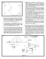
From inside the boat, connect the actuator cable leads to
the relay cable leads. Connect black to blue and red to
green. Route relay cable to battery area. Mount relay to
suitable surface within 3 feet of battery.
Connect relay cable to switch cable by aligning 3 prong
plug with 3 cavity plug and mating full closed. Route the
flexible cable so it is not touching any hot surfaces or
laying in water. Make final connection to battery. Connect
red cable to positive (+) terminal on battery. Connect black
cable to negative terminal (-). Test switch by pressing on
top side of rocker button.
Bracket should come up. If bracket fails to rise, check all
connections and check reset button on inline fuse at battery
connection. Press on bottom side of rocker button and
bracket will descend. (See Fig. 5.)
8. Mount outboard on Motor Bracket. Center motor left to
right and clamp in place. It is recommended that 25 hp
motors and larger be fastened in place with stainless steel
bolts and locknuts of a suitable size as recommended by
the manufacturer. Using the motor mounting bracket as a
drill guide, through drill the mounting board and bolt in
place. Check the location of the two lowest mounting holes
on your outboard. If, when drilled, they are too close to the
welded angle bracket on the opposite side to allow
clearance for a bolt head or nut, then drill a suitable tap
diameter hole, thread it and fasten with the bolt,
eliminating the nut.
FIG. 5
3


