
Mounting and Operating Instructions – Powered Auxiliary
Outboard Motor Brackets Models 71095 & 71096
Form 12.441
OPERATING INSTRUCTIONS
9. Press and hold the “up” switch. The motor and Bracket
should elevate and continue up until the actuator is fully
extended. Release Switch Note: the “whine” of the actuator
pump will change pitch when fully extended. Press and
hold the “down” switch. The motor and Bracket should
descend and continue until the actuator is fully retracted.
Release the switch. The stowed position while underway
with the main power is the full up position. If any part of
the lower unit is still in the water with the bracket in the full
up position, it is recommended that the motor be tilted to
clear the water. Note: It is recommended that the bracket
be in the full down position when using the auxiliary motor
that is mounted on it.
AUXILIARY OUTBOARD MOTOR BRACKET
IMPORTANT CAUTION GUIDELINES
1. Keep hands free of all moving parts.
2. Do not exceed stated weight or horse power.
3. Operate Bracket in lowest position possible for best
performance.
4. Operate motor at low speed.
5. Do not turn motor full left or right at full throttle as the
side forces could damage the Bracket and/or the boat
transom.
6. Always raise Bracket when not in use.
7. Always be aware of the motor and bracket extending
out the back of the boat when operating in and around
decks, slips and other boats.
8. Use of motor safety cable is highly recommended and
comes standard with 71095 (up to 25 HP).
SERVICE
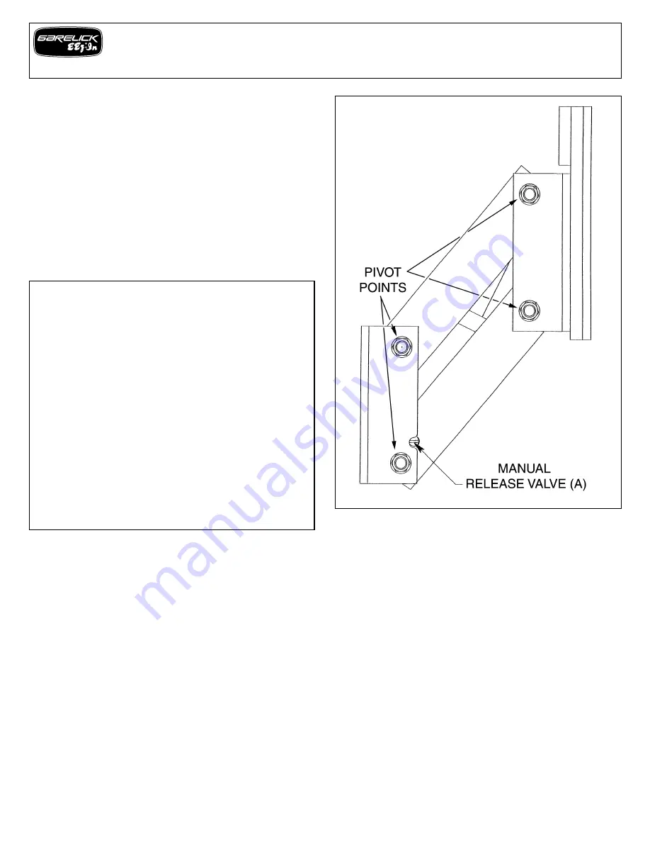
To minimize wear, keep all 8 pivot points well lubricated with a
medium to heavy lubricating oil/grease. In a salt water
environment, it is recommended the bracket is periodically
washed with soap and fresh water and waxed with a good
grade marine polish/wax.
MANUAL RELEASE VALVE
This Motor Bracket Actuator is equipped with a manual release
valve. In an emergency, if the power source is unable to operate
the actuator and the motor needs to be lowered to operating
height, the manual release valve may be turned 3 to 4 turns
counterclockwise and the bracket will lower itself. When Bracket
is full down, the Manual Release Valve (A) must be turned
clockwise until seated. (See Fig. 6)
FIG. 6
CAUTION:
Do not apply electrical power to Bracket with manual release
valve in the open position, as O-rings within the actuator will be
damaged.
BLEEDING THE ACTUATOR
The actuator is filled with Dextron 111 (ATF) at the factory and
should not need periodic service. However, if the Bracket fails to
stow in the full up position, it may be low on fluid. Lower the
bracket to a position where access to the filler cap is available
and remove the filler cap. Add Dextron 111 (ATF) if available,
or Quicksilver Power Trim and Steering Fluid, approximately 1
oz. at a time, to reduce the chance of over filling. L
eave the filler
cap off to allow any over fill to escape. Failure to follow these
instructions could cause permanent damage to the seals in the
actuator.
(Use appropriate means to protect the environment
and capture any over flow.) Cycle the bracket several times and
repeat if necessary. Replace and tighten filler cap when finished
(See Fig. 1 and 6).
4


