15
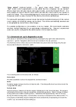
As camera skew relates to a particular camera
poise it is necessary to reset it to zero manually
and allow it to estimate a new value each time the camera is moved either deliberately or by
accident. Small lateral camera adjustments by sliding within the stroke of the supplied camera
bracket should not however require a reset, as camera poise should not be significantly affected.
A reset to zero is achieved by using arrow buttons to highlight reset and pressing the return button.
Caution
After resetting camera skew it will probably be necessary to adjust fine offset.
Camera skews in excess of 3 degrees indicate poor camera alignment requiring improvement.
Camera Offset (only present with multiple cameras on the same section)
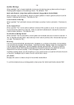
Camera offset is the lateral error between two or more cameras fitted to the same section. Like
skew it
is estimated by Robocrop’s computer programme during field operations. Rate of change
of this estimated displacement is highest during initial runs and after resetting to zero. It stabilizes
after running approximately 100m. There are as many offsets as there are cameras on a section.
The first camera is master from which offsets are derived and so it always has zero offset.
The purpose of estimating lateral misalignment and automatically compensating is to avoid the
need for very accurate mechanical setting up.
Camera skew relates to camera offset so that resetting skew resets both figures for all cameras
fitted. However, resetting offset does not automatically reset skew.
Custom colour (only present if enabled and custom colour selected)
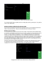
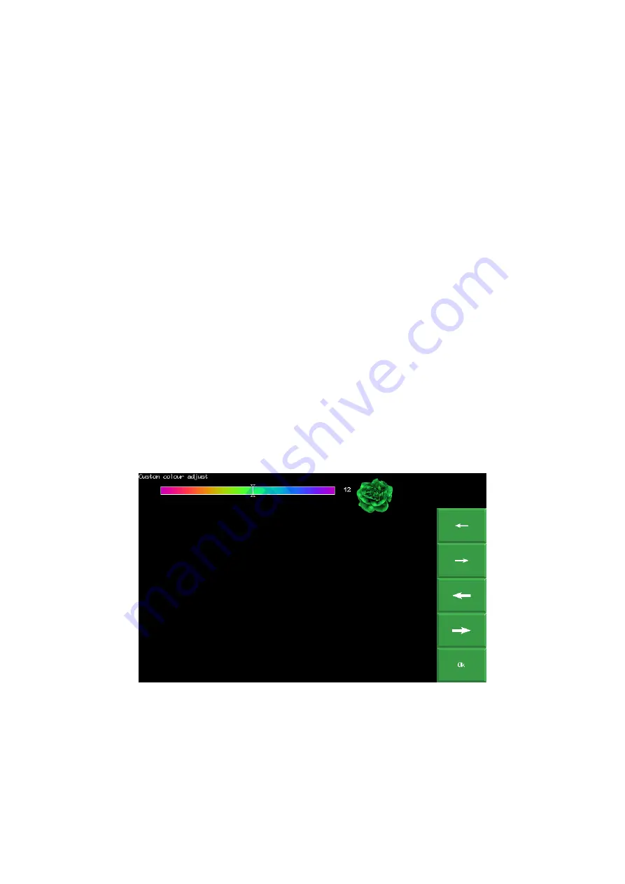
Selecting “adjust” provides a tool allowing users to bias the colour used for detecting plants. For
example, a small deviation from the standard green (0 on this scale) towards blue (e.g. 30) can
improve detection of some brassicas and alliums. Arrow keys shift the current selected colour
value which is reflected in plant icon colour. Large arrows move in steps of 10. Small arrows in
steps of 1.
Enabling custom colour is discouraged unless it is absolutely necessary as it adds complexity and
can, if not set correctly, dramatically reduce performance.
Test steering
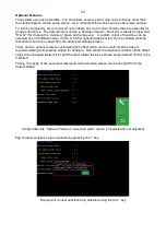
This test function checks a number of components and settings relating to side shift or steering
angle movement. Included are micro-controller communication with the main computer, direction
of hydraulic flow, rate of flow (too fast or too slow), correct side shift/disc potentiometer connection
polarity and continuity over the stroke. It also detects mechanical obstructions preventing full
travel. This is achieved by exercising the hydraulic cylinder and recording the response. It is
therefore necessary to turn the hydraulic supply on. For multi section machines you are prompted
to select which section to test.
Caution
Ensure the side shift/disc steering mechanism is clear of obstructions and people before running.

