19
Section settings
A section is defined as a frame that has independent steering. Most implements will have only one
section. However, it is possible to have an implement with multiple independently steered
sections. This is useful when it is required to span multiple drill/transplanter bouts.
The settings are;
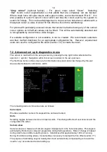
“Width” is the width of that section and is only used to calculate area worked,
“Peak travel” which is stoke of the side shift mechanism, “Pot scale” refers to calibration of the
linear potentiometer that measures side shift position and the final setting allocates which cameras
are fitted to that section.
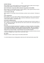
It is also possible to have settings (if appropriate defaults are installed) for disc steered machines.
For disc steer machines the second, third and fourth settings relate to; maximum angular deflection
from the central position, distance between the steering disc pivot axis and disc ground contact
point, and calibration of the rotary potentiometer that measures steer angle.
Configuration file “Section” standard editor screen
Camera settings
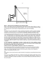
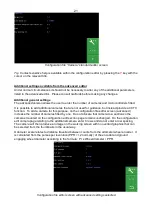
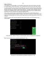
The first three settings relate to camera mounting geometry as illustrated below. Camera height is
the vertical distance in m (or inches with imperial units set) from ground level to the camera lens
when the implement is at its normal working height. Look ahead is the horizontal distance from a
point directly below the centre of the camera lens the centre of the image in the ground plane
(depicted by cross hairs in “manual” mode). “Distance ahead of cultivators” is the horizontal
distance in m (or inches with imperial units set) from a point vertically below the camera lens back
to the cultivator blades. (If In-row software is installed t
his distance is referred to as “Distance
ahead of rotors/nozzles” even if operating in inter-row mode)
“Look ahead” (m)
Height (m)
“Distance ahead of cultivators”
(m)


