background image

Part # 4521635 (03/04/08)

Page 16

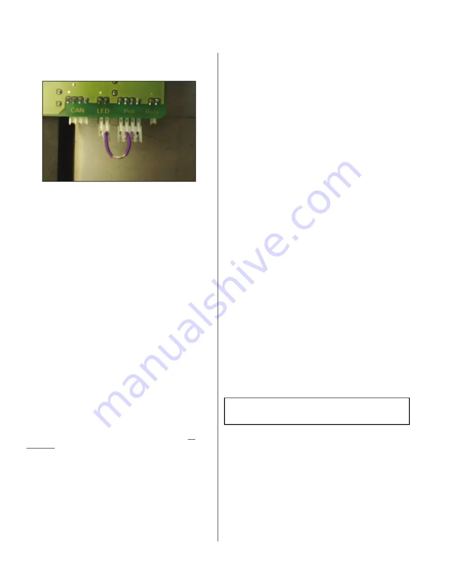
•  Place short circuit service plug into the power print board 

across the (Poti-LED) as showed in the photo below.

•  Connect the induction unit to the main power supply.

•  The CU sensors initialize automatically.

•  After successful initialization, the green LED on the small 

CPU-print (board) illuminates.

•  In case the system finds an error during initialization, the 

red LED will illuminate.

•  Disconnect the induction unit from the main power 

supply.

•  Check the CU sensors at the plug by means of the Ohm 

meter.

•  Re-start the procedure of initialization.

•  Disconnect the unit from the main power supply.

•  Remove the short circuit service plug from both the Poti 

and LED connections.

Initializing The Induction Unit  

By PC Or Laptop

The initialization of the CU (RTCS) sensors (

excluding all 

WOK models)

, as well as adjustments of the pan detection 

and power performance, can be performed by means of 

the hyperterminal program. Please refer to Section 9 “

IR 

Interface

” for instructions on how to use the hyperterminal 

program The following adjustments must be done in the 

hyperterminal program: 2400bps, 8bit, no parity, 1 stop bit, 

hardware protocol.

IMPORTANT NOTE

: When replacing the power board and 

or induction coil with RTCS sensors, you must reset all 

parameters.

IMPERATIVE! 

Pay close attention to whether you receive a 

feedback signal from the PC or Laptop after every change. 

This will be your signal that the change has been accepted 

successfully.

12345 Entry to the mode of adjustment (password)
;

Initialize Cu sensor (temperature of the coil ca. 

25°C/77°F) excluding WOK.

N

Increase the limit of the mains current (+)

n

Decrease the limit of the mains current (-)

Save the limit of the mains (power) current

T

Increase pan detector (+)

t

Decrease pan detector (-)

=

Save pan detector

-?

Leave the mode of adjustment

.

State software version

Change Of The Parameters

1.  Connect the RS232 connection cable to the  

PC/Laptop and straighten the IR-adapter to the left lower 

corner of the ceran glass. For counter top cookers, refer to 

Section (9) figure #3 for correct IR adapter positioning. For 

all Wok cookers, you will be required to remove the top 

wok bowl assembly. Place the IR-adapter in the left hand 

corner directly over the rectangular opening located on 

the metal sheet with ferrit stripes. Please refer to Section 

(9) figure #4 for Wok cooker IR adapter positioning. 

2.  Start HT2400 (see chapter 9) and turn unit on!

3.  Input “

12345

” and the mode of adjustment will now 

begin. The following message will appear on the monitor:

IR= On 

WELCOME REPAIRMEN

Summary of Contents for Enodis GIU-1.5 (BH/BA 1500)

Page 1: ...land Commercial Industries Inc SERVICE MANUAL INDUCTION COOKERS WITH RTCS TECHNOLOGY REAL TIME TEMPERATURE CONTROL SYSTEM COUNTER TOP BUILT IN WOK MODELS IMPORTANT NOTE INDUCTION COOKERS MANUFACTURED...

Page 2: ...tallic Plates 6 Power Rating 7 Fan 7 Test Of The Components 7 Rectifier 7 Transistor module IGBT 8 CU RTCS Sensors 8 Potentiometer 8 SECTION 5 MAINTENANCE SERVICE 9 SECTION 6 FAULT FINDING 12 General...

Page 3: ...as all inspections are performed by authorized and qualified personnel Before attempting to operate the equipment carefully read the information and instructions outlined in the Installations and Oper...

Page 4: ...rrent A max 16 14 5 max 16 Power factor Cos 0 95 0 95 0 95 Discharge rate mA 4 4 4 Coil mm 190 7 5 190 7 5 190 7 5 Model SH IN Built in Models 208 V 1 Ph 240 V 1 Ph 208 V 3 Ph Wattage kW 3 5 kW 3 5 kW...

Page 5: ...sition of the control knob to 0 and then to the required power level See Error Message Section 6 Power board The temperature of the power board is checked by a temperature sensor As soon as the heat s...

Page 6: ...the material structure of the pan or its efficiency In some cases the magnet will attach itself to the bottom of the pan however the pan may not be suitable for use with induction cooking Always use...

Page 7: ...at 2 Measure the time until the fan starts working 9 12 The fan should start working after 6 8 minutes 3 Go on cooking for about 30 minutes 9 12 The heating process may periodically be interrupted for...

Page 8: ...rt circuit or an interruption the IGBT transistor is defective and must be replaced CU RTCS Sensors CU Sensor 1 Center 4 5 5 Ohms CU Sensor 2 Outer 4 5 5 Ohms The two CU sensors are mounted directly o...

Page 9: ...once a year The following routine maintenance should and must be completed periodically Fan Function of the cooker can only be guaranteed if all electronic components are operated within their normal...

Page 10: ...ot make contact with the high voltage section on the power board Coil wires must be tightly twisted together and precisely placed Coil terminals must be connected in the direction shown in photo Gener...

Page 11: ...Incorrect Coil Spoil Connections Coil wires not twisted tightly together or precisely placed Coil terminals connected in the incorrect direction Coil terminals connected in the incorrect direction Co...

Page 12: ...code 1 8 The indicator lamp located directly above the control knob flashes for an interval of 0 6 seconds The number of the following short flashes have to be counted in order to determine the type...

Page 13: ...ms at 25 C 77 F 19 CU sensor 2 high temperature warning a Temperature of the cooking field too high b Turn the power down 20 Power reduction generator inside temperature a Check for heat sources aroun...

Page 14: ...K Check electric Potential DC Volts Defective Check IGBT Transistor s Replace Power board Error Check fuse T1A OK Check power Print board visually Check wiring Error Correct wiring connections Wired i...

Page 15: ...ht side Lift cover with the glass Remove M4 screws remove coil carrier Remove PT sensor and coil connections SECTION 8 ADJUSTMENT OF PROCESS PARAMETERS The induction unit excluding all WOK units with...

Page 16: ...TE When replacing the power board and or induction coil with RTCS sensors you must reset all parameters IMPERATIVE Pay close attention to whether you receive a feedback signal from the PC or Laptop af...

Page 17: ...tector with the key On the console appears the message please confirm Press the key again The following message appears on the monitor save pan detector limit 9 By input the mode of adjustment will be...

Page 18: ...60006 SH BA 3500 240VAC 1N 3 5kW GIU 3 5 185 23 99560007 SH BA 5000 208VAC 3N 5kW GIU 5 0 167 21 99560008 SH BA 5000 400VAC 3N 5kW GIU 5 0 99560009 SH BA 5000 440VAC 3N 5kW GIU 5 0 99580004 SH IN 3500...

Page 19: ...laptop computer Place the IR sensor section onto the ceran glass towards the bottom left hand corner for counter top cookers Position the IR sensor to the generator Refer to figure 3 in this section...

Page 20: ...ld be saved so that there will be no need to put them again and the connection can be built up by selecting symbol IR2400 ht Figure 3 IR Adapter position for counter top base line cookers For all coun...

Page 21: ...ter position for built in install line cookers IR Adapter to be positioned directly over rectangular opening shown in photo IR Adapter tool in position Place Wok Bowl top assembly back onto cooker as...

Page 22: ...CHEMATIC Main Power Filter L1 L2 L3 PE 230V L2 208V L2 240V L2 AC DC Power Supply 12VAC 24VDC 5VDC 5VDC GND Rectifier AC DC 12VAC 5VDC 24VDC T B 24VDC Potentiometer LED IR Adapter Fan CPU IGBT Transis...

Page 23: ...Part 4521635 03 04 08 Page 23...

Page 24: ......

Reviews: