background image

4517957 Rev. 2 (06/05)

Page 15

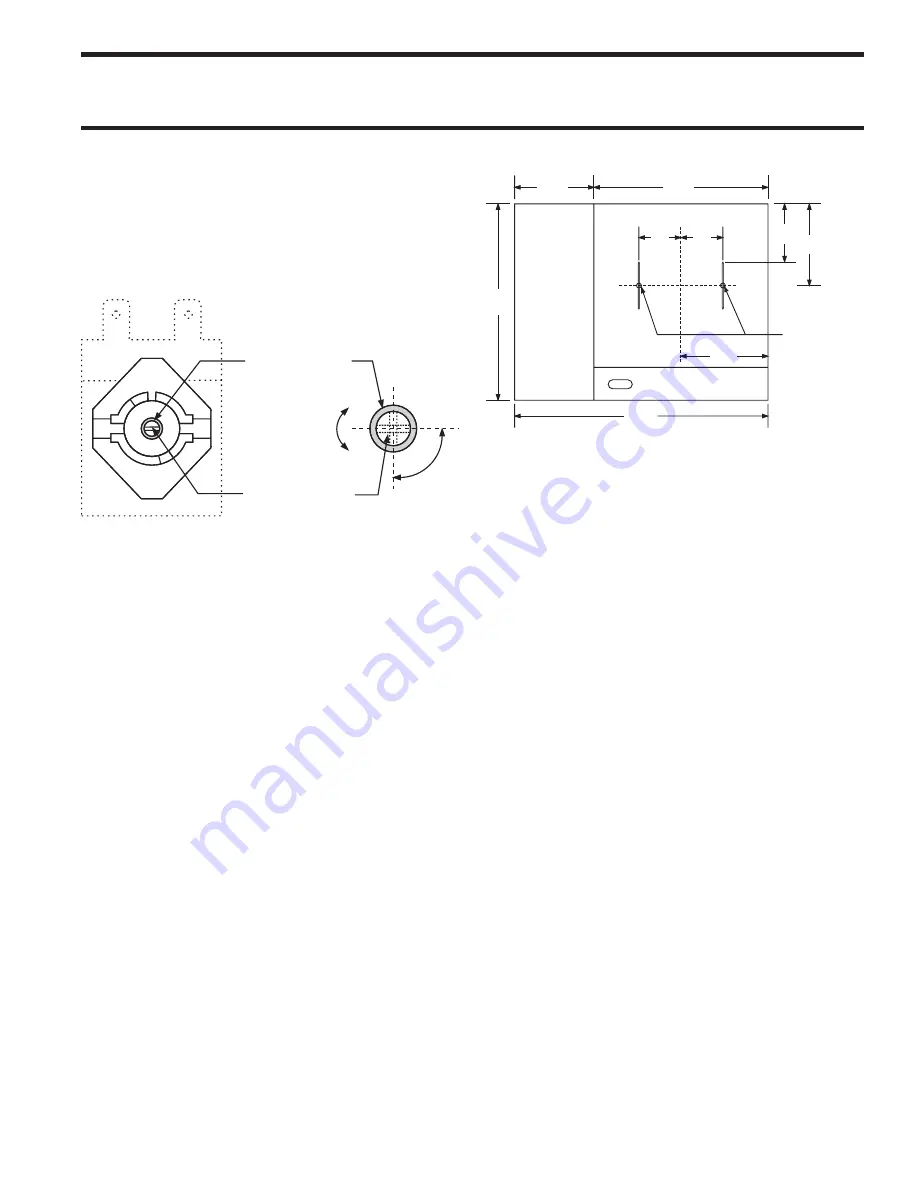
36.0

28.0

24.0

12.0

12.0

6.0

6.0

11.5

Place

Thermocouple

Here

TOP VIEW

FRONT

GRIDDLE

HOT TOP

7.3

ref.

To find the location of the sensing bulbs, locate the exact  

center of the griddle. Measure 6" to the left and 6" to the  

right. Place the temperature sensor there.

3.  Check the griddle temperature when the thermostat 

just  cycles  “OFF”  by  placing  the  thermocouple 

firmly  on  the  griddle  surface  directly  above  the 

sensing bulb of the thermostat. (see the following 

diagram for how to find the location directly above 

the thermostat sensing bulb) The reading should be 

between 285°F and 315°F. If the reading is outside 

of these limits, calibrate as follows:

4.  Carefully remove the thermostat dial, not disturbing 

the dial setting.

5.  Hold the thermostat shaft steady and with a small 

flat blade screw driver, turn the calibration screw 

located inside the  shaft  clockwise  to decrease the 

temperature  and  anti-clockwise  to  increase  the 

temperature. Note: Each 1/4 turn of the screw will 

create a change of approximately 25°F.

6.  Replace  the  thermostat  dial  and  repeat  steps  1 

through  3  to  verify  that  correct  adjustment  has 

been made.

MAINTENANCE & CLEANING continued

3.  Check  the  temperature  reading  just  when  the 

control cycles “OFF” as indicated by cycling pilot 

lamp. If the temperature does not read within 15°F 

of the dial setting, recalibrate as follows:

4.  Carefully remove the thermostat dial, not disturbing 

the dial setting.

"B" Dial Shaft

1/4

Turn

Decrease

Increase

"A" Calibration

Screw Head

5.  Hold the thermostat shaft steady and with a small 

flat blade screw driver, turn the calibration screw 

located inside the  shaft  clockwise  to decrease the 

temperature  and  anti-clockwise  to  increase  the 

temperature. Note: Each 1/4 turn of the screw will 

create a change of approximately 25°F.

6.  Replace  the  thermostat  dial  and  repeat  steps  1 

through  3  to  verify  that  correct  adjustment  has 

been made.

Griddle

1.  Use  a  test  instrument  with  a  special  disc  type 

thermocouple or a reliable surface type pyrometer. 

Note:  a  drop  of  oil  on  the  face  of  the  disc  will 

provide better contact with the plate.

2.  Set  all  griddle  thermostats  to  300°F.  In  order  to 

allow  the  griddle  temperature  to  stabilize,  the 

thermostats must be allowed to cycle twice before 

taking a test reading.

Summary of Contents for SRW286A

Page 1: ...smells gas This information shall be obtained by consulting your local gas supplier Users are cautioned that maintenance and repairs must be performed by a Garland authorized service agent using genui...

Page 2: ...4517957 Rev 2 06 05 Page...

Page 3: ...en 11 Convection Oven 12 Lighting the Oven 12 Shut Down 12 Operating Suggestions 12 MAINTENANCE CLEANING 12 Stainless steel 12 Exhaust Filter 13 Enameled Painted Surfaces 13 Griddle 13 Cleaning instru...

Page 4: ...T 10 POWER CORD AT REAR 120V FAN GUARD 10 1 2 267mm 1 1 2 38mm 3 3 4 95mm 3 1 2 83mm 39 1 2 1003mm 28 711mm 5 127mm 12 305mm 24 610mm 36 915mm 45 1 2 1156mm 31 3 4 806mm 5 127mm 20 1 2 521mm 3 4 NPT R...

Page 5: ...tenance Periodic inspections by the dealer or a qualified service company are recommended to check temperature burner adjustments and to ensure moving parts are operative Wherever possible avoid overh...

Page 6: ...on on the data plate of your new equipment must match your fuel supply When corresponding with the factory or equipment dealer regarding service problems or replacement parts be sure to refer to the p...

Page 7: ...el floor designed to withstand the weight of the fully laden appliance Any openings in the wall beside the appliance should be sealed Appliances Equipped with Casters The installation shall be made wi...

Page 8: ...E C Manifold Pressure Injector Size BURNER NATURAL GAS PROPANE Manifold Pressure Injector Size Manifold Pressure Injector Size mbar W C DMS mm mbar W C DMS mm GRIDDLE 11 2 4 5 42 2 4 25 10 53 1 51 HOT...

Page 9: ...ired opening per table E on the previous page Adjust if necessary FIXING SCREW SHUTTER OPENING MEASUREMENT INJECTOR LOCATION Hot Top Minimum Flame Setting 1 Set the gas tap to the MIN position 2 Conne...

Page 10: ...griddle surface as this will scratch or nick the surface and will result in improper cooking or sticking of the product Never salt food over the griddle since this will build up a gummy residue makin...

Page 11: ...The recommended pre heat time is 30 minutes This will thoroughly saturate the plate Pots must have flat bottoms for maximum contact with the hot surface Roasting pans with straps should never be used...

Page 12: ...the O position when the range is not in use 2 Clean the range as soon as possible after cooking tomato or vinegar based products that have a high acid content These foods can cause pitting of the sur...

Page 13: ...d water Replace Cleaning Instructions For Heavy Build Up NOTE After using cleaners grease cutter re season the griddle NOTE Apply to a warm griddle for best results 1 Using a traditional 2 5 3 64mm 76...

Page 14: ...t and slide the burner and burner pan forwards out of the combustion chamber 6 Clean the burner with a stiff scrubbing brush and shake the burner well to ensure that ports are clear of any debris 7 Re...

Page 15: ...5 F 6 Replace the thermostat dial and repeat steps 1 through 3 to verify that correct adjustment has been made MAINTENANCE CLEANING continued 3 Check the temperature reading just when the control cycl...

Page 16: ...new spring supplied Upon completion of all the above operations follow the section in the manual on Commissioning and ensure that the setting pressure and all burner flame settings are adjusted accor...

Page 17: ...rubbing on oven baffle Adjust blower wheel Blower wheel loose on motor shaft Retighten blower wheel Defective motor Replace motor Cook Cool Down switch set to Cool Down motor not working Defective Coo...

Page 18: ...when the oven doors are opened Control Panel Rocker Switches 1 Remove the fastener securing the control compartment access panel REPLACEMENT OF PARTS 2 Slide out the control drawer to access the switc...

Page 19: ...plate to the oven casing back and pull the plate forward into the oven compartment 6 Disconnect the motor wire connections note which wire connects to which and replace faulty motor 8 Reassemble in th...

Page 20: ...Specify Gas 1 5 4518183 Pilot Bracket Oven 1 6 22701XX Oven Orifice Fitting 3 53 SHT 1 OF 2 SK3894 55 56 54 81 54 57 47 27 31 46 52 51 50 49 43 113 114 115 112 111 110 109 106 107 118 102 101 100 103...

Page 21: ...1730296 Front Frame Assy 1 27 2621300 Body Side Support 2 28 2614100 Body Side R H 1 29 2642000 Wall Shield 1 30 2604200 Inner Liner 1 31 1309021 Body Side Insulation 5 Thick Burglas 1200 2 32 3020000...

Page 22: ...75 1 69 1439901 Oven Door Panel 1 70 3077100 Nameplate 1 71 3017000 Handle 1 72 4516836 120V Cooling Fan Assembly 1 4517669 230 V Cooling Fas Assembly 1 73 3007300 Handle End 2 74 3010000 Handle End P...

Page 23: ...151 153 168 185 184 154 159 158 160 161 156 155 164 6 157 170 172 171 173 174 201 177 176 179 178 163 181 182 183 166 165A 167 186 189 190 191 188 193 194 195 196 217 119 222 221 219 220 215 213 208 1...

Page 24: ...Spring PRO 1 110 2622400 Wiring Access Cover 1 111 4517369 Control Compartment Back 1 112 2490500 Straight Thru Relief Bushing Domestic Model 1 113 1029600 Antishorts 2 114 1029400 3 8 BX Cable 1 115...

Page 25: ...sy 1 155 2617500 Orifice Support Hot Top 1 156 M8 XX Orifice Hood Hot Top Specify Gas 1 157 G02486 00 Orifice Fitting less Hood Hot Top 1 158 2200700 SIT Pilot RH 1 158A 2200704 3 16 Comp Nut 1 158B 2...

Page 26: ...riddle Pilot RH 1 186 4517062 Front Rail 1 187 4517039 Heat Shield Hot Top Valve 1 188 G03053 1 Momentary Push Button Switch 1 189 4516937 Handle Assy 1 190 4517048 Valve Panel 1 191 4517416 Switch Bo...

Page 27: ...230V 4 outlet 1 4514750 Spark Generator 120V 4 outlet 1 226 3050401 Terminal Block Export Model 1 227 4517052 BX Connector Retainer 1 229 G03883R Thermoflex Insulating Sleeve 1 230 2200203 High Tensio...

Page 28: ...33 33 34 34 35 36 38 37 38 35 36 37 41 40 39 42 39 40 41 42 43 44 45 46 43 44 45 31 29 30 18 19 11 12 E1 F1 E2 F2 F3 E3 46 1434533 1431528 1431531 1431526 1431526 1431526 1431526 E4 47 48 48 49 48 49...

Page 29: ...6 38 37 38 35 36 37 41 40 39 42 39 40 41 42 43 44 45 46 43 44 45 31 29 30 18 19 11 12 E1 F1 E2 F2 F3 E3 46 1434533 1431528 1431526 1431526 1431526 1431526 E4 47 48 48 49 48 49 55 55 5 7 49 53 52 14 50...

Page 30: ...OOLING FAN ALL DIMENSIONS ARE IN INCHES TOLERANCE 0 015 UNLESS OTHERWISE SPECIFIED TITLE DATE SCALE DR SHT OF CHK BY REV REV DATE DR DESCRIPTION REVISIONS M COOK COOL OFF NO NC COM RL1a RL1 RL1b 12 6...

Page 31: ...4A SPARK ELECTRODE HOT TOP PB IGNITION MODULE HOT TOP COOLING FAN warning light thermodisc ALL DIMENSIONS ARE IN INCHES TOLERANCE 0 015 UNLESS OTHERWISE SPECIFIED TITLE DATE SCALE DR SHT OF CHK BY RE...

Page 32: ......

Reviews: