GMA 1347D Installation Manual
Page 4-7
190-00303-21
Revision
C
4.3.3 RS-232 Serial Input/Output
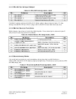
Table 4-5. RS-232 Pin Assignments, J3472
Pin Pin
Name
Description
I/O
6
RS-232 OUT 1
Output level greater than ±5 Volts
Out
7
RS-232 IN 1
Input level up to ±25 volts
In
38
RS-232 OUT 2
Output level greater than ±5 Volts
Out
39
RS-232 IN 2
Input with level up to ±25 volts
In
The RS-232 outputs conform to EIA/TIA-232C with an output voltage swing of at least ±5 V when
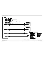
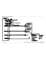
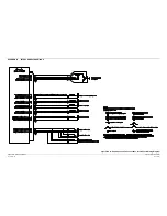
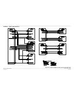
driving a standard RS-232 load. Refer to Figure B-5 for the RS-232 serial data interconnections.
4.3.4 Marker Beacon Functions
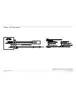
Marker Beacon connections are listed in the following table. The antenna input is connected to pins 78
(HI or Center Conductor) and 59 (LO or Shield).
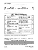
Table 4-6. Marker Beacon Pin Assignments, J3472
Pin Pin
Name
Description I/O
34
MIDDLE MARKER SENSE
2.5-8 Vdc into 4.7 k
Ω
Out
74
AIRWAY/INNER MARKER EXT
LAMP OUT (-00)
MKR I-HI white 2.5-8 Vdc into 56
Ω
Out
75
MIDDLE MARKER EXT LAMP OUT
MKR M-HI amber. 2.5-8 Vdc into
56
Ω
Out
76
OUTER MARKER EXT LAMP OUT
MKR O-HI blue. 2.5-8 Vdc into 56
Ω
Out
78
MARKER ANTENNA HI
Marker antenna input, 50
Ω
In
59
MARKER ANTENNA LO
Ground reference for pin 78
--
4.3.5 Reversionary Mode
The reversionary mode pins are used in installations having more than one GDU that have a
GMA 1347D. The GMA 1347D contains a display backup button. This button is used to switch the PFD
and MFD display data.
Table 4-7. Reversionary Mode Pin Assignments, J3472
Pin Pin
Name
Description
I/O
36
REVERSIONARY MODE 1
PFD
connect
Out
37
REVERSIONARY MODE
COMMON 1
Ground reference for mode 1
--
56
REVERSIONARY MODE 2
MFD
connect
Out
57
REVERSIONARY MODE
COMMON 2
Ground reference for mode 2
--


