GMA 1347D Installation Manual
Page 4-9
190-00303-21
Revision
C
4.4
J3471 Connector Pin Assignments
This section covers the pin connections of J3471 only.
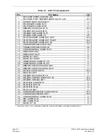
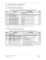
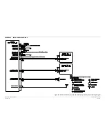
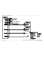
4.4.1 Mic Audio Inputs and Mic Keys
Table 4-11. Mic Audio Inputs and Mic Key Pin Assignments, J3471
Pin Pin
Name
Description
I/O
29
PILOT MIC KEY* IN
Enables audio into the respective
transceiver unit
In
28
PILOT MIC AUDIO IN HI
In
30
PILOT MIC IN LO
Pilot Mic audio input and ground reference
In
46
PASS 1 MIC AUDIO IN HI
In
47
PASS 1 MIC AUDIO IN LO
Passenger 1 Mic audio and ground
reference
In
65
PASS 2 MIC AUDIO IN HI
In
66
PASS 2 MIC AUDIO IN LO
Passenger 2 Mic audio and ground
reference
In
44
PASS 3 MIC AUDIO IN HI
In
45
PASS 3 MIC AUDIO IN LO
Passenger 3 Mic audio and ground
reference
In
63
PASS 4 MIC AUDIO IN HI
In
64
PASS 4 MIC AUDIO IN LO
Passenger 4 Mic audio and ground
reference
In
* Denotes Active Low (Inputs: ground to activate; Outputs: grounded when active).
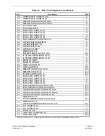
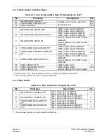
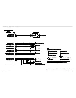
4.4.2 Remote ICS Audio and ICS Keys
Table 4-12. Remote ICS Audio and ICS Keys Pin Assignments, J3471
Pin Pin
Name
Description I/O
31
PILOT ICS KEY*
In
24
PASS ICS KEY*
Enables audio into the intercom system
In
21
REMOTE CREW ICS AUDIO IN HI
In
22
REMOTE CREW ICS AUDIO IN LO
Remote crew ICS input and ground
reference
In
40
REMOTE PASS ICS AUDIO IN HI
In
41
REMOTE PASS ICS AUDIO IN LO
Remote passenger ICS input and
ground reference
In
60
REMOTE CREW ICS OUT HI
Remote crew audio output
Out
5
REMOTE PASS ICS AUDIO OUT
HI
Remote passenger audio output
Out
61
REMOTE CREW ICS OUT LO
Ground reference for remote passenger
and crew audio outputs
Out
* Denotes Active Low (Inputs: ground to activate; Outputs: grounded when active).

