background image


10 


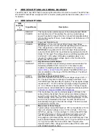
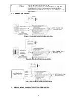
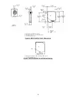
WIRE DESCRIPTIONS AND WIRING DIAGRAMS 

The GPS 15xL-F and GPS 15xH-F use an eight contact flex circuit LIF connector. The GPS 15xL-

W and GPS 15xH-W use an eight pin JST connector (mating wire harness included). (See

 1.5.1.3


for details.) 

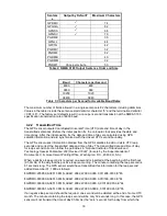
2.1  WIRE DESCRIPTIONS 

GPS 

15xH/15x

L  

Pin # 

Signal Name 

Description 

BACKUP 

POWER 

This input provides external power to the battery-backed SRAM 

and real-time clock. This enables the user to provide backup 

power if needed for longer than the on-board rechargeable battery 

will provide (roughly 21 days). Input voltage must be b2.8 

and +3.4 Vdc. 

GROUND 

Power and Signal Ground 

POWER 

GPS 15xL: 

+3.3 to +5.4 Vdc (±100 mV ripple) input. Peak 

operating current is 100 mA. Nominal operating current is 85 mA. 

This voltage drives an LDO with a nominal 3.0 Vdc output. 

GPS 15xH: 

Unregulated 8.0 to 40.0 Vdc input. Peak operating 

current is 40 mA @ 12 Vdc input. Nominal operating current is 33 

mA @ 12 Vdc input. This voltage drives a switching regulator with 

a nominal 3.3 Vdc output. Although a regulated supply is not 

required, the peak-to-peak voltage ripple on this line should be 

kept to less than 100 mV. 
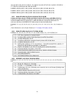
PORT 1 

DATA OUT 

Asynchronous Serial Output. 

RS-232 compatible output normally provides serial data which is 

formatted per 

NMEA 0183, Version 2.0

. This output is also 

capable of outputting phase data information; see 

Appendix B: 

Garmin Binary Output Format 

for details. The NMEA 0183 baud 

rate is selectable in the range of 300 to 38400 baud. The default 

baud rate is 4800. 

PORT 1 

DATA IN 

First Asynchronous Serial Input. 

RS-232 compatible with maximum input voltage range of -25 < V < 

25. This input may also be directly connected to standard 3 to 5 

Vdc CMOS logic that uses RS-232 polarity. The low signal voltage 

requirement is < 0.6 Vdc, and the high signal voltage requirement 

is > 2.4 V. Minimum load impedance is 500 

Ω

. This input may be 

used to receive serial initialization/ configuration data as specified 

in 

Section 4.1 Received NMEA 0183 Sentences.
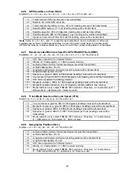
 

RF BIAS 

This input allows the user to externally apply an RF bias to the 

active antenna. By default, the unit will use an internal voltage to 

power the active antenna. If an external voltage greater than the 

internal voltage of the center pin of the antenna (between 3.5 Vdc 

and 8.0 Vdc) is detected at this input, the GPS 15xH/15xL will 

automatically changes to the external voltage. The antenna must 

not draw more than 60 mA. 

MPO 

Measurement Pulse Output. 

Typical voltage rise and fall times are 300 ns. Impedance is 150 

Ω

Open circuit output voltage is low = 0 Vdc and high = Vin in the 

GPS 15xL, and low = 0 Vdc and high = 5.0 Vdc in the GPS 15xH. 

The default format is a 100 ms wide active-high pulse at a 1 Hz 

rate; the pulse width is configurable in 20 ms increments. The 

rising edge is synchronized to the start of each GPS second. This 

output provides between 800 mVp-p to 1.7 Vp-p for GPS 15xL and 

1.4 Vp-

p for the GPS 15xH into a 50 Ω load. The pulse time 

measured at the 50% voltage point will be about 50 ns earlier with 

a 50 Ω load than with no load.


Summary of Contents for 15 H Series

Page 1: ...GPS 15xH 15xL TECHNICAL SPECIFICATIONS 190 00266 03_0B December 2023...

Page 2: ...his manual without obligation to notify any person or organization of such changes or improvements Go to www garmin com for current updates and supplemental information concerning the use of this prod...

Page 3: ...15 4 1 3 Sensor Configuration Information PGRMC 15 4 1 4 Additional Sensor Configuration Information PGRMC1 16 4 1 5 Output Sentence Enable Disable PGRMO 16 4 2 Transmitted NMEA 0183 Sentences 17 4 2...

Page 4: ...to the Sensor 38 File Menu 39 Comm Menu 39 Config Menu 39 View Menu 40 Help Menu 40 LIST OF TABLES AND FIGURES Table 1 GPS 15xH 15xL Wire Descriptions Error Bookmark not defined Figure 1 Computer Ser...

Page 5: ......

Page 6: ...ion If this equipment does cause harmful interference to radio or television reception which can be determined by turning the equipment off and on the user is encouraged to try to correct the interfer...

Page 7: ...xL F 8 pin LIF Low Insertion Force flex connector 1 millimeter pitch For use with common 1 mm pitch 8 conductor flex cable available as Garmin Part Number 310 00040 01 This flex cable mates with commo...

Page 8: ...38 seconds initial position time and almanac known ephemeris unknown Cold Approx 45 seconds 1 6 4 3 Update Rate 1 second default NMEA 0183 output interval configurable from 1 to 900 seconds in 1 seco...

Page 9: ...Cable Garmin Part Number 010 10121 00 is used Place the MCX to BNC Adapter Cable between the connector on the end of the antenna cable and the connector on the GPS 15xH 15xL Noise Figure Gain The tot...

Page 10: ...3 baud rate is selectable in the range of 300 to 38400 baud The default baud rate is 4800 5 PORT 1 DATA IN First Asynchronous Serial Input RS 232 compatible with maximum input voltage range of 25 V 25...

Page 11: ...ormatted per RTCM SC 104 Recommended Standards For Differential Navstar GPS Service Version 2 2 see Section 4 5 for more details 2 2 WIRING DIAGRAMS Figure 1 Computer Serial Port Interconnection Figur...

Page 12: ...s inches 2 Dimension tolerance 0 25 mm 0 01in 3 Use M2 mounting screws Figure 4 GPS 15xH F 15xL F Dimensions 1 Dimensions identical to GPS 15xH F and GPS 15xL F 2 Use M2 mounting screws Figure 5 GPS 1...

Page 13: ...by the GPS sensor must be terminated with CR LF Please note that CR and LF denote the ASCII characters for carriage return 0D hexadecimal and line feed 0A hexadecimal respectively So CR and LF are ea...

Page 14: ...14 14 af0 clock parameter 15 af1 clock parameter...

Page 15: ...error is detected the echoed PGRMC sentence will contain the current default values Current default values can also be obtained by sending PGRMCE CR LF or PGRMCE 0E CR LF to the GPS sensor PGRMC 1 2...

Page 16: ...ld is not used on the GPS 15xH 15xL and is included only for compatibility with other models 11 No Effect This field is not used on the GPS 15xH 15xL and is included only for compatibility with other...

Page 17: ...ily PGRMO G CR LF will cause the COM port to change to Garmin Binary Output mode for the duration of the power cycle or until 10 0A 02 26 00 CE 10 03 Hexadecimal is sent to the GPS receiver in order t...

Page 18: ...n obtained from the GPS satellites to add or delete UTC leap seconds and correct the transmitted date and time of day The transmitted date and time of day for leap second correction follow the guideli...

Page 19: ...PGGA 1 2 3 4 5 6 7 8 9 M 10 M 11 12 hh CR LF 1 UTC time of position fix hhmmss format 2 Latitude ddmm mmmm format leading zeros will be transmitted 3 Latitude hemisphere N or S 4 Longitude dddmm mmmm...

Page 20: ...ding zeros will be transmitted 8 Course over ground 000 0 to 359 9 degrees true leading zeros will be transmitted 9 UTC date of position fix ddmmyy format 10 Magnetic variation 000 0 to 180 0 degrees...

Page 21: ...nsmitted 7 Latitude hemisphere N or S 8 Longitude dddmm mmmm format leading zeros must be transmitted 9 Longitude hemisphere E or W 10 Mode M Manual A Automatic 11 Fix type 0 no fix 1 2D fix 2 3D fix...

Page 22: ...22 4 2 14...

Page 23: ...xL and is included only for compatibility with other models 9 No Effect This field is not used on the GPS 15xH 15xL and is included only for compatibility with other models 4 2 16 3D Velocity Informat...

Page 24: ...s 14 BERMUDA 1957 Bermuda Islands 15 BOGOTA OBSERVATORY Colombia 16 CAMPO INCHAUSPE Argentina 17 CANTON ASTRO 1966 Phoenix Islands 18 CAPE CANAVERAL Florida Bahama Islands 19 CAPE South Africa 20 CART...

Page 25: ...ding San Salvador Island 57 NORTH AMERICAN 1927 Central America Belize Costa Rica El Salvador Guatemala Honduras Nicaragua 58 NORTH AMERICAN 1927 Canal Zone 59 NORTH AMERICAN 1927 Canada including New...

Page 26: ...ito Santo Island 88 SAO BRAZ Sao Miguel Santa Maria Islands Azores 89 SAPPER HILL 1943 East Falkland Island 90 SCHWARZECK Namibia 91 SOUTHEAST BASE Porto Santo and Madeira Islands 92 SOUTHWEST BASE Fa...

Page 27: ...The second byte identifies the record type 33 hex for a position record and 72 hex for a satellite data record The third byte indicates the size of the data The fourth byte is the first byte of data T...

Page 28: ...uble gps_tow double lat double lon float lon_vel float lat_vel float alt_vel float msl_hght int leap_sec long grmn_days cpo_pvt_data alt Ellipsoid altitude meters epe Estimated position error meters e...

Page 29: ...atic char in_que 256 static int in_que_ptr 0 static rx_state_type rx_state DAT void add_to_que char data define DLE_BYTE 0x10 define ETX_BYTE 0x03 if rx_state DAT if data DLE_BYTE rx_state DLE else in...

Page 30: ...from the data sent in step 4 This value will be within 5 of the actual baud rate For example the GPS unit might send a baud rate of 38361 which correlates to a baud rate of 38400 6 If the baud rate i...

Page 31: ...in Garmin binary format transmitted and received packets are structured as follows Byte Description Name Notes Packet Delimiter DLE 0x10 Packet ID type ID Packet type Data Size SIZE Number of bytes in...

Page 32: ...f bytes in data SIZE 0x02 Request to D L ephemeris IOP_CMND_DATA 0x0A Pad DATA 0x00 Checksum calculation CHKSUM Delimiter DLE 0x10 End of packet ETX 0x03 Then the unit will immediately send a packet c...

Page 33: ...16 wn week number weeks float toc reference time of clock parameters s float toe reference time of ephemeris parameters s float af0 clock correction coefficient group delay s float af1 clock correctio...

Page 34: ...loat m_TempArray IDX_EPH_AF2 pTemp EphStruct ura float m_TempArray IDX_EPH_URA cnvt_ieee_double long m_TempArray IDX_EPH_E pTemp EphStruct e double m_TempArray IDX_EPH_E cnvt_ieee_double long m_TempAr...

Page 35: ...efine IDX_EPH_OMG0 68 define IDX_EPH_I0 76 define IDX_EPH_ODOT 84 define IDX_EPH_IDOT 88 define IDX_EPH_CUS 92 define IDX_EPH_CUC 96 define IDX_EPH_CIS 100 define IDX_EPH_CIC 104 define IDX_EPH_CRS 10...

Page 36: ...OT uninstall this device Solution 2 Do not plug the DB9 connector into the computer until the computer is turned on and the operating system is completely booted up and running Every time you use the...

Page 37: ...he box next to Garmin Binary Output to change the GPS 15xH 15xL to Garmin Mode The unit will keep this change in the programming until you change it again in the software Note Selecting Config Switch...

Page 38: ...pening the program SNSRXCFG exe the following screen appears Select the radio button next to the type of Garmin sensor you are configuring and click OK Connecting to the Sensor After selecting the typ...

Page 39: ...his manual for clarification about some of these fields This window is primarily used to enter a new Latitude Longitude and Altitude for the sensor This is especially helpful when you are programming...

Page 40: ...ou to view the NMEA 0183 sentences transmitted by the sensor You can also customize how the program looks by showing and hiding the Toolbar and Status Bar Help Menu The Help Menu displays the software...

Reviews: