Garmin AT
Rev --
© 2004 Garmin AT
GX Service Manual
7-25
Comm Test Procedures
Tests and procedures for troubleshooting a defective GX Comm board and returning it to service are
described in this section. The first section, a test data sheet, is presented in a generic format and lists
and summarizes the tests that are needed to return the unit to service. The second section describes
the return to service procedures specifically when using the HP8920 test set.
Test Data Sheet – Comm Return to Service
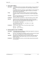
1. Display and Controls
Display and controls are accessed using the test mode. Test mode can also change calibration
functions stored during manufacture or service. Do not change or adjust any functions while in the
test mode unless specifically instructed to do so in this manual.
The SL display is used during display and control tests. The SL display can be connected
standalone. Refer to Test Equipment Setup on page 7-17 for details.
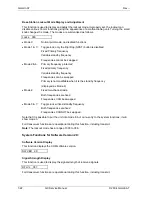
Test Mode Page
Enable the built-in test mode by pressing the NRST and SYS buttons on the SL display while
switching the unit on.
In test mode operation, the large knob is used to select the different test functions; the small knob
is used to select additional pages for each test function.
The Test Mode Page is the first page displayed in the test mode.
TEST MODE
When this page is displayed, pressing the MSG button will return the COM to normal mode
operation.
The large knob is not tested in this function. It is tested by default by selecting the various test
functions.
Display test function: _____ OK
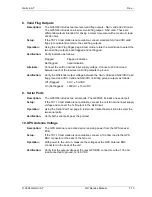
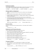
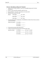
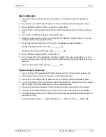
2. Transmitter Tests
Power Out:
1. Connect a wattmeter to the antenna output and record the following unmodulated power
levels.
2. 13.8 VDC (+/- 5%) Power supply:
25°C + 4°
-20°C + 4°
+55°C + 4°
118.00MHz ____8 watts min.
118.00MHz ____7 watts min.
118.00MHz ____7 watts min.
126.5MHz ____8 watts min.
126.5MHz ____ 7 watts min.
126.5MHz ____7 watts min.
135.97MHz ___ 8 watts min.
135.97MHz ___ 7 watts min.
135.97MHz ___ 7 watts min.
3. 10.0 VDC (+/- 5%) Power supply:
118.00MHz ___ 6 watts min. 126.5MHz ____6 watts min. 135.97MHz ___ 6 watts min.
Summary of Contents for APOLLO GX SERIES
Page 8: ...Garmin AT Rev viii GX Service Manual 2004 Garmin AT This Page Intentionally Left Blank...
Page 12: ...Garmin AT Rev 1 4 GX Service Manual 2004 Garmin AT...
Page 24: ...Garmin AT Rev 2 12 GX Service Manual 2004 Garmin AT...
Page 26: ...Garmin AT Rev 3 2 GX Service Manual 2004 Garmin AT...
Page 27: ...2004 Garmin AT GX Service Manual 4 1 Chapter 4 Antenna Installation Guides...
Page 28: ...Garmin AT Rev 4 2 GX Service Manual 2004 Garmin AT...
Page 32: ...Garmin AT Rev 5 4 GX Service Manual 2004 Garmin AT...
Page 96: ...Garmin AT Rev 7 58 GX Service Manual 2004 Garmin AT...
Page 98: ...Garmin AT Rev 8 2 GX Service Manual 2004 Garmin AT Figure 8 1 GX55 Assembly Board Locations...
Page 122: ...Garmin AT Rev 8 26 GX Service Manual 2004 Garmin AT...
Page 130: ...Garmin AT Rev 9 8 GX Service Manual 2004 Garmin AT...
Page 140: ...Garmin AT Rev 10 10 GX Service Manual 2004 Garmin AT Figure 10 5 Comm Board Block Diagram...
Page 152: ...Garmin AT Rev 10 22 GX Service Manual 2004 Garmin AT...
Page 158: ...Garmin AT Rev 11 6 GX Service Manual 2004 Garmin AT...
Page 160: ...Garmin AT Rev 12 2 GX Service Manual 2004 Garmin AT...
Page 162: ...Garmin AT Rev 13 2 GX Service Manual 2004 Garmin AT...
Page 165: ......
Page 166: ......

