Garmin AT
Rev --
© 2004 Garmin AT
GX Service Manual
7-55
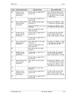
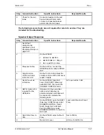
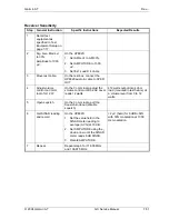
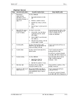
Final Unit Checkout
After the unit has passed both the NAV and Comm return to service procedures, perform the
following final unit test procedures. The unit must be fully assembled and properly connected to the
TST 10 test station. Operate the GX50/55/60/65 in the test mode by holding down the leftmost and
rightmost “smart keys” while switching on the power. To return to normal operation, switch the power
off, then back on.
1. Avionics Outputs
Check the avionics output connections by using the test mode as follows. Rotate the large knob
to select each test.
1. Select the CDI Triangle page, rotate the small knob to check left, mid, and right.
2. Select the VDI Triangle page, rotate the small knob to check down, mid, and up.
3. Select the To/From Flag page, rotate the small knob to check the Off, To, and From outputs.
4. Select the Lamp Outputs page, rotate the small knob to check all the connected
annunciators.
5. Select the Valid Flag Pages page, rotate the small knob to check all the connected valid flag
outputs.
2. Installation Configuration
The GX50/55/60/65 must be configured to match the operation supported by the installation. This
includes IFR, VFR, approach, and Search and Rescue operation selections.
1. In test mode, rotate the large knob to the Install Options page.
2. Press SEL. Rotate the small knob to select IFR operation (Yes or No). Rotate the large knob
for APPR* selection. Rotate the small knob to select approach operation (Yes or No). Rotate
the large knob for SAR (Search and Rescue) selection. Rotate the small knob to select SAR
operation (Yes or No). Press ENTER
when complete. (Note: APPR can only be set to Yes
when IFR is set to Yes).
*
(GX50/60 only)
3. Serial Interface Configuration
The GX50/55/60/65 RS-232 serial ports can be configured for several input and output formats.
To select the serial port configurations:
1. In test mode, rotate the large
knob to the serial port configuration “CH RX TX” page.
2. Press SEL (the selection fields will start flashing), rotate the large knob to select the port, rotate
the small knob to select the desired configurations, then press ENTER when complete.
4. Comm Radio Setup
The Test Mode settings may also be used to preset the Microphone (Mic) Gain and the Receiver
Squelch levels.
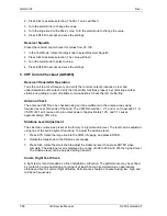
Mic Gain
Set the microphone gain for microphones 1 and 2 for values from 0 to 255.
1. In the Test Mode, rotate the large knob to select Mic Gain.
Summary of Contents for APOLLO GX SERIES
Page 8: ...Garmin AT Rev viii GX Service Manual 2004 Garmin AT This Page Intentionally Left Blank...
Page 12: ...Garmin AT Rev 1 4 GX Service Manual 2004 Garmin AT...
Page 24: ...Garmin AT Rev 2 12 GX Service Manual 2004 Garmin AT...
Page 26: ...Garmin AT Rev 3 2 GX Service Manual 2004 Garmin AT...
Page 27: ...2004 Garmin AT GX Service Manual 4 1 Chapter 4 Antenna Installation Guides...
Page 28: ...Garmin AT Rev 4 2 GX Service Manual 2004 Garmin AT...
Page 32: ...Garmin AT Rev 5 4 GX Service Manual 2004 Garmin AT...
Page 96: ...Garmin AT Rev 7 58 GX Service Manual 2004 Garmin AT...
Page 98: ...Garmin AT Rev 8 2 GX Service Manual 2004 Garmin AT Figure 8 1 GX55 Assembly Board Locations...
Page 122: ...Garmin AT Rev 8 26 GX Service Manual 2004 Garmin AT...
Page 130: ...Garmin AT Rev 9 8 GX Service Manual 2004 Garmin AT...
Page 140: ...Garmin AT Rev 10 10 GX Service Manual 2004 Garmin AT Figure 10 5 Comm Board Block Diagram...
Page 152: ...Garmin AT Rev 10 22 GX Service Manual 2004 Garmin AT...
Page 158: ...Garmin AT Rev 11 6 GX Service Manual 2004 Garmin AT...
Page 160: ...Garmin AT Rev 12 2 GX Service Manual 2004 Garmin AT...
Page 162: ...Garmin AT Rev 13 2 GX Service Manual 2004 Garmin AT...
Page 165: ......
Page 166: ......


