background image

Getting Started

This section explains how to get started using your
Apollo GX. Information in this section explains how
to:

·

Select a waypoint

·

Store waypoints

·

Find a Nearest Waypoint

·

Fly Direct-To a waypoint

·

Create a flight plan

·

Activate a flight plan

·

Use the Moving Map

It is necessary to enter a seed position and the current
time the

first time

you turn the unit on. This should

have been done when your unit was installed. So, you
won’t have to set it again unless the unit has been
moved several hundred miles with the power off.

Power On

Turn the Power knob clockwise to switch the unit on.
The startup screen, testing, position, and database
information shows on the display for several seconds
and then will go into the Navigation function.

Select a

Waypoint

You can search for a waypoint character by character,
sort through the database by selecting the first few
characters of the identifier to simplify the search, or
look at every waypoint in order. You can search for
waypoints by identifier or the city/facility name.

Finding a waypoint by name

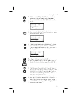
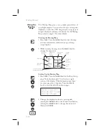
1. Press the

DB

smart key. Turn the

LARGE

knob to

display the Access Database page. Press

ENTER

.

Access Database

Press ENTER

Getting Started

2-1

DB

ENTER

Summary of Contents for Apollo GX50

Page 1: ......

Page 2: ...s of Garmin AT Inc 2003 by Garmin AT Inc All rights reserved Printed in the U S A Garmin AT Inc Consumer Products Division 2345 Turner Road S E Salem OR 97302 U S A Toll Free 800 525 6726 Canada Toll...

Page 3: ...the comm features of the GX60 but is not IFR approach certified and does not have the approach features You can be confident in knowing that you are the owner of the state of the art in aviation navig...

Page 4: ...pproach User s Guide Insert 560 0928 xx GX60 65 Comm User s Guide Insert 560 0963 xx User s Guide Binder 1 560 9000 User s Guide Binder 3 4 560 9002 User s Guide Binder 1 1 4 560 9008 User s Guide Bin...

Page 5: ...sonable protection against harmful interference during residential use Operation is subject to the following two conditions 1 this device may not cause harmful interference and 2 this device must acce...

Page 6: ...t keys A hard key is a permanent key on the right side of the front panel The NAV key example shown here is a hard key The smart keys are five small keys below the display The key label is shown above...

Page 7: ...by selected characters 2 2 Looking at all waypoints in a database 2 3 Duplicate Identifier City or Facility Names 2 4 Waypoint Information 2 4 Storing a Waypoint 2 5 Finding a Nearest Waypoint 2 6 Fly...

Page 8: ...cial Use Airspace 3 13 Altitude Assist VNAV 3 14 Parallel Track Offset 3 19 GPS Position 3 21 Countdown Timer 3 22 Arc Assist 3 23 Waypoint Distance Page 3 25 Waypoint ETE Page 3 25 From To Next Waypo...

Page 9: ...aypoint Type Selection 4 6 Track History 4 8 Airspace Setup 4 10 Airspace Buffers 4 11 ATC Ring Selection 4 12 Airspace Selections 4 12 Search and Rescue 4 14 Search and Rescue Map Description 4 14 Gr...

Page 10: ...Pos 5 12 Delete User Waypoint 5 12 Modify User Waypoint 5 13 Creating Waypoint Comments 5 14 Deleting Waypoint Comments 5 15 Update User Waypoint 5 16 Datacard 5 16 RNAV Waypoints 5 16 Flight Plan Fun...

Page 11: ...Time 7 1 Navigation Mode Programmable and Autonav Pages 7 2 Customizing Navigation Pages 7 2 Selecting Autonav Pages 7 4 Restoring Default Nav Pages 7 4 Lat Lon Units 7 4 Setting Units of Measurement...

Page 12: ...New Messages 8 2 Old Messages 8 2 Messages 8 3 Approach Basics GX50 60 9 1 Introduction 9 1 En Route 9 1 Approach Transition 9 2 Approach Active 9 2 Approach Transition 9 2 Waypoint Arrival Alert 9 2...

Page 13: ...9 Approach Example 2 Holding at IFAF 9 44 Approach Example 3 Missed Approach 9 51 Approach Example 4 VOR Reference 9 56 Manual Flight Plan Leg Selection Example 9 61 Approach Example 5 DME Arc 9 63 Ap...

Page 14: ...ass 11 1 Quick Comm GX60 65 Only 11 1 Comm Radio Test GX60 65 11 1 Owner Message 11 2 Memory Tests 11 2 Database Message 11 5 Seed Position 11 5 Entering a Seed Position 11 5 IFR Output Tests 11 8 Che...

Page 15: ...se features serve the needs of today s demanding aviation requirements The large waypoint database has information about airports VORs NDBs intersections and special use airspaces that makes the Apoll...

Page 16: ...r possesses all of the performance features of the GX55 plus more The GX50 is TSO C129a Class A1 JTSO C129a Class A1 authorized for IFR non precision approach operation The GX50 uses the same tray siz...

Page 17: ...he power on Rotate the knob fully counterclockwise to turn the power off Full rotation and the push pull capabilities are only used in the GX60 65 Power Volume Squelch Knob GX60 65 The knob on the rig...

Page 18: ...ard Keys The Hard keys are the easy touch black rounded keys with white lettering on the right side of the display These keys include NAV NRST INFO SEL MAP Direct To and ENTER NAV Navigation Press the...

Page 19: ...specialized functions Five small unlabeled keys are located below the display The labels appear on the display and can change to give extra controls for the active function such as in the MAP function...

Page 20: ...smart key to control the display of the waypoint type There are three selections possible waypoint identifier and location symbol location symbol only and off Pressing the smart key subsequent times w...

Page 21: ...Setup Keys The Map Setup page displays three smart keys that provide a short cut for customizing your moving map The Route Line smart key toggles between On and Off See page 4 4 for more details The M...

Page 22: ...e you are transmitting or editing in any function RCL Recall GX60 65 Press the RCL key to recall frequencies stored in the database MON Monitor GX60 65 Press the MON key to listen to the Standby frequ...

Page 23: ...on Parallel Track Nearest Waypoint Search Internal Database of Airports VORs NDBs Intersections Frequencies Airport Info and controlled and special use airspace GPS Receiver Performance Specifications...

Page 24: ...ansmit GX50 and GX60 65 Avionics Outputs CDI L R deviation 150 mv full scale TO OFF FROM flag 250 mv TO FROM indication Nav valid flag 300 mv for valid indication Nav superflag 400 ma source VDI up do...

Page 25: ...ute Humidity 95 at 50 C for 6 hrs 2 day cycle Maximum altitude 55 000 feet Cooling Not required VHF Comm Features GX60 65 760 channels Frequency range of 118 000 to 136 975 MHz Active and standby freq...

Page 26: ...de VHF Comm Transceiver Performance Specifications GX60 65 Class 4 Output Power 8 watts minimum carrier at 12 VDC 6 watts minimum at 10 VDC transmit is locked out below 9 VDC input Modulation capabili...

Page 27: ...ndred miles with the power off Power On Turn the Power knob clockwise to switch the unit on The startup screen testing position and database information shows on the display for several seconds and th...

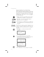
Page 28: ...bout that waypoint or press DIRECT TO and then ENTER to fly directly to it Sorting waypoints by selected characters 1 Press the DB smart key Turn the LARGE knob to display the Access Database page Pre...

Page 29: ...and ccw to check the waypoints AIRPORT FCA KALISPELL city dup MT USA Looking at all waypoints in a database 1 Press the DB smart key Turn the LARGE knob to display the Access Database page Press ENTER...

Page 30: ...duplicates 3 If the information is still duplicated press INFO and turn the SMALL knob to view information about the waypoint Waypoint Information The GX series contains a wealth of information in it...

Page 31: ...ot allowed to use a USER waypoint as the Radial and Distance reference waypoint This example will create a Lat Lon based USER waypoint For more details on waypoints see the Waypoint Database section o...

Page 32: ...icated waypoint Near 1 to PPos SLE AIRPORT Brg 352 5 4nm 2 Turn the LARGE knob to view the different waypoint types Near 1 to PPos UBG VOR Brg 344 26 6nm 3 Turn the SMALL knob to view the 20 nearest w...

Page 33: ...waypoint 3 After selecting the desired waypoint press ENTER Your Apollo GX will now switch to the Navigation function and show information based on a direct route from your present position to the Di...

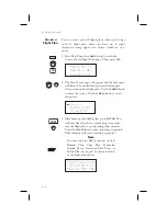
Page 34: ...flight plan Use the LARGE knob to move the cursor Use the SMALL knob to select characters ________ Enter a New Plan Name 3 After naming your flight plan press ENTER You will now have the choice of ins...

Page 35: ..._ ____ 7 The identifier will be entered and the TO waypoint position for the first flight plan leg will have a flashing Ins prompt Continue entering waypoints into your flight plan Press SEL to quit i...

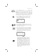
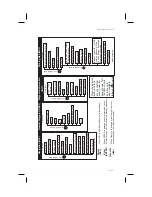
Page 36: ...MAP Turn the LARGE knob to the Map Setup page Note the diamond in the lower right corner of the display This diamond means there are more pages for a function Turn the SMALL knob to view the other Map...

Page 37: ...on INFO Turn LARGE Knob ETE BRG RAIM Prediction Altitude Assist Parallel Track PTK GPS Position Countdown Timer Arc Assist To Next Wpt Distance To Next Wpt ETE To Next Wpt ETA From To Next Waypoint Tu...

Page 38: ...Autonav Time Lat Lon Units Program Nav Pages Mag Var Flight Timer Trigger Direct To CDI Scaling Turn LARGE Knob System SYS System Info Date Time Test Display Display Brightness Owner Name Model SW Ve...

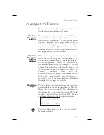
Page 39: ...mation displays and sequencing rate are user programmable See the Nav info section of the System Functions chapter see page 7 1 for your options The LARGE knob will select the higher level Nav functio...

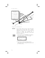
Page 40: ...2 1 10 Brg 082 74nmY 2 Stop Autonav rotation by pressing any key or turning either knob Leaving the Nav function will also disable Autonav 3 2 Navigation Basics ENTER TO WPT FROM WPT North Track Angle...

Page 41: ...Brg 010 39 7nm Nav Pages The Apollo GX provides a wide variety of navigation information This information is provided on a number of displays that you can view by turning the LARGE knob Some displays...

Page 42: ...lue will be dashed if the FROM or TO waypoints are blank or the GPS receiver does not have a valid position Range Rge The distance from your present position to the TO waypoint Units can be set as eit...

Page 43: ...0 nm full scale 5 0 nm A single dot thickness bar indicates that CDI sensitivity is set to 0 3 nm full scale per side The two dot bar indicates a sensitivity of 1 0 nm full scale per side The three d...

Page 44: ...egree increments and is updated in reference to your present position The Leg distance shown 42 4 nm is the current FROM TO distance DTK varies with Turn Anticipation page 3 36 and DME Arcs page 9 26...

Page 45: ...to 359 degrees in one degree increments Track Angle Error is computed using the magnetic variation at the Present Position The Track Angle Error value will be dashed if the FROM or TO waypoints are b...

Page 46: ...rived by taking the altitude of the highest obstruction within the grid rounded up to the next 100 feet and adding 300 feet For example if the highest obstruction is 4 728 feet the MEF would show as 5...

Page 47: ...e current Ground Speed from the present position The TO waypoint is displayed Units are hours and minutes 00 00 to 23 59 based on the UTC 24 hour clock The values will be replaced with dashes if the s...

Page 48: ...esent position The Bearing and Distance to the displayed waypoint is shown on the right side of the display Press DIRECT TO and then ENTER to set the displayed waypoint as the new destination TO waypo...

Page 49: ...R The Nearest waypoints and airspaces will now be referenced to the selected search waypoint rather than your present position Near 1 to SLE SLE AIRPORT Brg 110 0 5nm 5 Turn the SMALL knob to view the...

Page 50: ...ength of 0 feet means you will accept any runway length Choosing a runway length for instance of 5 000 feet will not show an available airport with a runway length less than 5 000 feet either for a Ne...

Page 51: ...around your present position the first ten airspaces within 100 miles are displayed While searching for airspaces the keys and knobs are disabled and the following display will appear Searching for A...

Page 52: ...aircraft moves and the following display may appear Re Organizing Airspaces Please Wait Altitude Assist VNAV Altitude Assist provides guidance for your vertical navigation needs Altitude Assist featur...

Page 53: ...he default barometric pressure setting is 29 92 If an Air Data Sensor is installed and provides corrected baro altitude barometric altitude will be displayed instead of the altimeter setting Altitude...

Page 54: ...old Altitude value will flash Hold Alt 5650ft Buffer 150 ft ENT to Hold Alt 2 Turn the SMALL knob to change the value 3 Turn the LARGE knob to the Buffer value Turn the SMALL knob to change the value...

Page 55: ...ore you should begin Auto Descent and once Auto Descent begins whether you are above or below your intended Glide Path Glide Path data may also be output to an optional Vertical Deviation or HSI Glide...

Page 56: ...knob to the destination waypoint field Turn the SMALL knob cw or ccw to change the field You can choose from the remaining waypoints in your flight plan 3 Turn the LARGE knob to the Ending Altitude v...

Page 57: ...course and the offset distance The PTK annunciator if installed will turn on when Parallel Track is enabled When Parallel Track is selected the course line drawn on the Map pages will show the parall...

Page 58: ...distance values are what you want press ENTER If you want to change the direction or distance turn the LARGE knob to choose the direction or distance fields Parallel Track Offset Use RIGHT 12 4nm 3 A...

Page 59: ...nm GPS Position The GPS Position page shows the calculated Latitude and Longitude as well as its Position Dilution of Precision PDOP The PDOP value shown below PDOP is based on the geometry of the sat...

Page 60: ...n the Navigation function turn the LARGE knob to view the Countdown Timer page 2 Press SEL to start editing The minutes value will flash Countdown Timer 00 03 00 3 Turn the LARGE knob to move between...

Page 61: ...er the desired track for the arc and the distance to the reference waypoint The Arc Assist reference waypoint defaults to the nearest VOR unless you have already selected one Press ENTER to accept the...

Page 62: ...Arc Assist You can select the reference waypoint for the Arc Assist feature and it can be used at any time not just during approach or terminal operations It can also be used for difficult operations...

Page 63: ...abase or the data card has been removed aSLE nm aPDX 43nm aSEA 154nm Waypoint ETE Page This page displays the cumulative time in hours and minutes from your current position to each waypoint in the ac...

Page 64: ...nge the Active Flight Plan and vice versa You may also Hold sequencing suspended or enable the TO waypoint Note Your flight plan will be placed on Hold while you are editing the FROM TO NEXT waypoints...

Page 65: ...MALL knob AIRPORT AAF APALACHIOCOLA city FL USA 4 Turn the LARGE knob to the first character of the waypoint name The first character of the waypoint name will flash Turn the SMALL knob to select the...

Page 66: ...have selected the desired waypoint From EUG arpt To ______ Next ______ B Set the TO Waypoint 1 Press SEL and move to the TO waypoint with the LARGE knob The insert Ins choice will flash Press ENTER a...

Page 67: ...Ins 2 After selecting a NEXT waypoint press ENTER From EUG arpt To SLE arpt Next HIO arpt D Editing FROM TO NEXT Waypoints 1 While in the Navigation function turn the LARGE knob to view the FROM TO NE...

Page 68: ...O designation with the LARGE knob You can also place the TO waypoint on hold by pressing the external WPT SEQ or GPS SEQ button when it is installed You can also place a waypoint on Hold in the Flight...

Page 69: ...you press DIRECT TO the default waypoint shown will be the current TO waypoint in the Nav or Flight Plan functions or the waypoint displayed in the Database or Info functions Function DIRECT TO Waypo...

Page 70: ...ect To Examples The following three examples provide some of the more common ways that you can use the powerful Direct To function Center the CDI After changing your course to avoid weather an obstacl...

Page 71: ...want to temporarily go to a new waypoint to look at something or you may be directed by ATC By using Direct To you can add this new waypoint into your existing flight plan This way your flight plan i...

Page 72: ...MINNVILLE city OR USA 3 Press ENTER The Nav function will now be displayed with your new TO waypoint MMV ete aMMV 00 20 0 011 Brg 321 15 6nm 4 Check your active flight plan pages Press FPL Turn the S...

Page 73: ...ack field is coupled to your HSI CDI Your HSI CDI is being read by the SL30 at the same time Rotating the control on your HSI CDI will update the OBS Desired Track on your Apollo GX You can override t...

Page 74: ...ack are determined based on the turn Turns are made at three degrees per second if the ground speed is under 250 knots If ground speed is greater than 250 knots the turn rate is set at 1 5 degrees per...

Page 75: ...ind conditions requiring steeper than maximum bank angles may result in overshooting the new course line GPSS GPS Steering GPSS information is provided by your Apollo GX when setup with a properly ins...

Page 76: ...rawn for these Fly over waypoints The GPSS information from your Apollo GX will handle this automatically GPSS Rules There a few rules for providing valid GPSS information to your autopilot Your autop...

Page 77: ...nd speed The Distance Speed and Time to waypoint information is sent by the Apollo GX for display on your Apollo SL30 The pilot should verify the station identification prior to navigation use Nav Ide...

Page 78: ...oded Localizer identifier to the Apollo GX The Apollo GX searches its LOC DME database for an identifier match If the Localizer is found to be a co located LOC DME the Apollo GX will provide Distance...

Page 79: ...of the display The TO waypoint identifier is shown in reversed text on the upper left corner The bearing from your current position to the TO waypoint is shown on the upper right corner The map scale...

Page 80: ...A solid reversed waypoint type annunciator above the smart key means the waypoint identifier and location symbol will both be displayed A bold outline of the waypoint type annunciator will show only a...

Page 81: ...he screen in nautical miles Map scale choices in nautical miles are 0 1 0 2 0 5 1 2 5 10 15 20 30 40 50 75 100 150 200 250 and auto The auto selection automatically adjusts the map scale so the TO rem...

Page 82: ...ap Setup page Press SEL to start selection of the Route Line The Route Line selection will flash Or press the RTE smart key to toggle through the choices Route Line On Map Orient North Map Ref Plane 4...

Page 83: ...top of the display The aircraft symbol is at the bottom of the display and will point towards the direction you are flying Track Up The direction that your aircraft is moving towards is at the top of...

Page 84: ...int Type Selection The Identifier Waypoint Type page allows you to choose the type of waypoint identifiers that will be displayed on the moving map You may control the look of your map screen for each...

Page 85: ...type that you want to edit Turn the SMALL knob to choose symbol and identifier ID symbol only or Off In this example the flashing underlined selection would show both the symbol and identifier for in...

Page 86: ...ory is full The Clear Track selection allows you to clear the existing track history memory whenever you select Yes The used value shows the percentage of track history used Track History function has...

Page 87: ...00 5 Press ENTER when you have completed your selections 6 Turn the SMALL knob clockwise to the second Track History page Press SEL to start selection or press the appropriate smart key The Strategy...

Page 88: ...es for Airspace Setup On this page you may select whether Airspaces are shown on the Map display or whether Airspace Alerts are provided Press SEL to start selection The Map choice will flash Turn the...

Page 89: ...ls From the Map Setup page turn the SMALL knob three clicks cw to reach the Airspace Buffers page 1 While viewing the Airspace Buffer page press SEL The distance value will flash Airspace Buffers Dist...

Page 90: ...ge press SEL to start selection 5 nm ATC Rings Map Off 2 Turn the SMALL knob to choose ON or OFF Press ENTER after completing your selection 5 nm ATC Rings Map On Airspace Selections The Airspaces ava...

Page 91: ...the map or alert selections are set to off The Map MAP and Alert ALE smart keys also select the options 1 While viewing the Map Setup page turn the SMALL knob to the Airspace Setup page Turn the SMALL...

Page 92: ...ch and Rescue Map Description The Search and Rescue map page is essentially the same as the regular full map with the addition of the SAR features However at various zoom levels underlying waypoint in...

Page 93: ...on lines section number and quarter section lines GRD 4 Section lines section number quarter section lines and quarter section letters 4 15 Moving Map Functions 20 27 3 010T T aTTD 426 423 394 393 20...

Page 94: ...SEL to allow selection of the Search and Rescue feature Turn the SMALL knob to set the SAR Map value to ON or OFF When SAR Map is set to ON the SAR Map will be available When set to OFF the SAR Map w...

Page 95: ...c Grid type select the Position quadrant NW SW NE or SE with the SMALL knob or the POS smart key Quadrant lines are defined by the Equator Prime Meridian and the International Date Line For example th...

Page 96: ...e Position location refers to the LAT LON of the southeast starting corner for the selected grid SAR Position Latitude 40 Longitude 120 2 Press SEL and use the SMALL and LARGE knobs to set the grid po...

Page 97: ...N 36 00N 125 00W 118 00W 448 28 Las Vegas LAS 40 00N 35 45N 118 00W 111 00W 476 28 Denver DEN 40 00N 35 45N 111 00W 104 00W 476 28 Wichita ICT 40 00N 36 00N 104 00W 97 00W 448 28 Kansas City MKC 40 00...

Page 98: ...attern type Press ENTER to choose the pattern and to start selecting the available options Parallel Line Search Page Press ENTER 3 Select the desired options and press ENTER 4 Press ENTER to activate...

Page 99: ...ing Set direction Activate pattern 1 While viewing the SAR Map page press the PAT smart key 2 Turn the SMALL knob to select the Parallel Line pattern type if necessary Press ENTER 3 Press SEL to start...

Page 100: ...the Direction of Travel option Turn the SMALL knob to select the desired Direction of Travel You may select N S or E W 7 Press ENTER when selections are complete 8 Press ENTER to activate the search p...

Page 101: ...path You may select the following options Starting Waypoint Pattern spacing Direction of travel in 1 degree increments Leg length Starting Side 1 While viewing the SAR Map page press the PAT smart ke...

Page 102: ...You may select between 0 2 and 9 9 nm Start PFC arpt Spacing 1 0 Direction 000 6 Turn the LARGE knob to the Direction of Travel option Turn the SMALL knob to select the desired Direction of Travel Yo...

Page 103: ...h pattern Leg Length 8 0 Start RIGHT Side 11 Press ENTER to accept the selected values Leg Length 8 0 Start LEFT Side 12 Press ENTER again to activate the search pattern You will automatically return...

Page 104: ...es and at an angle selected for the Direction of Travel You may select the following options Starting Waypoint Pattern spacing 0 2 to 9 9 nm Direction of travel in 1 degree increments 1 While viewing...

Page 105: ...d 9 9 nm Start ONP arpt Spacing 5 0 Direction 000 6 Turn the LARGE knob to the Direction of Travel option Turn the SMALL knob to select the desired Direction of Travel You may select a direction from...

Page 106: ...th the current Lat Lon position The default waypoint name will be SAR000 the first time Subsequent User waypoints will automatically increment to SAR001 SAR002 etc SAR002 USER 44 30 48N 123 36 09W 3 Y...

Page 107: ...id type on the SAR Setup page to have this display available 1 Press the DB smart key Turn the LARGE knob to the Create User Wpt By US Grid page Press ENTER Create User Wpt by US GRID Press ENTER 2 Th...

Page 108: ...Basic Grid coordinate as a User waypoint You can then fly Direct To the starting point in a grid for flying a search pattern You must have selected the Basic Grid type on the SAR Setup page see page...

Page 109: ...sions The second letter C notes the 15 grid division 1 Press the DB smart key Turn the LARGE knob to the Create User Wpt By Basic Grid page Press ENTER Create User Wpt by BASIC GRID Press ENTER 2 The...

Page 110: ...the SMALL knob to choose the User waypoint type if necessary 2 Use the LARGE and SMALL knobs to select the desired waypoint 3 Press ENTER 4 Navigate to the selected grid Setting Up A Search Pattern T...

Page 111: ...tions INTs User created USERs Available Waypoint Information The following information is available for each waypoint type Use the waypoint INFO function to get this information as the Introduction de...

Page 112: ...fier name state country Bearing and distance from present position Map Operating frequency Lat Lon coordinates Sunrise Sunset time Waypoint comment LOC DME Waypoint Information Identifier name country...

Page 113: ...ing Emergency Search or creating a Flight plan This section will describe going directly into the database the other methods of using the waypoint database will be covered in the sections about the sp...

Page 114: ...X AIRPORT PORTLAND city OR USA 5 You can also select the waypoint by the facility name As you turn the LARGE knob to the city facility field PDX AIRPORT PORTLAND city OR USA Multiple duplicate facilit...

Page 115: ...own after selecting the waypoint and pressing INFO Home Page This is the page where the waypoint is selected from the Access Database page The waypoint type identifier city facility name state provinc...

Page 116: ...e waypoint In the GX60 65 the center three smart keys indicate the available frequencies Press the smart key to load the indicated frequency into the Standby position SLE ATIS 124 55 UNIC 122 95 TWR 1...

Page 117: ...by pressing SEL and then turning the SMALL knob Press SEL again to disable map scaling Runway Info Turn the SMALL knob to view runway information For each runway the length type and lighting are shown...

Page 118: ...times by pressing SEL and then using the SMALL and LARGE knobs Press ENTER if desired to hold the date 07 Nov utc time SLE Rise15 05 arpt set 00 46 Waypoint Comment Turn the SMALL knob to view the Wa...

Page 119: ...function see page 3 12 1 Press the DB soft key Turn the LARGE knob to view the Create User Wpt By Lat Lon page and then press ENTER Create User Wpt by Lat Lon Press ENT 2 The first character of the wa...

Page 120: ...NT 2 The first character of the radial will flash Ref Wpt AAF 000 0 000 0nm 3 Select the Reference Waypoint Turn the LARGE knob ccw one click to select the waypoint identifier which will be replaced b...

Page 121: ...SLE 040 0 012 0nm 6 Press ENTER when you have finished entering the waypoint information You will be prompted to create a name for the waypoint 000 USER 44 10 96N Rwlen 121 43 35W 0000 7 Now use the...

Page 122: ...aypoint identifier will flash Turn the SMALL knob to choose the User waypoint you want to change Press ENTER Find wpt to set AA user Press ENTER 4 The User waypoint information is displayed next Press...

Page 123: ...ss ENTER Modify User Wpt Press ENT 2 Turn the SMALL knob to view the User waypoints Find WPT to Mod CABIN user Press ENT 3 When the waypoint to modify is displayed press ENTER The first character of t...

Page 124: ...while viewing the Info for any waypoint 1 While viewing the desired waypoint press INFO Turn the SMALL knob to the Waypoint Comment page and press SEL Waypoint Comment Press SEL 2 The first character...

Page 125: ...5 used Press ENT 2 Press ENTER to view the waypoint comments The first waypoint comment page will show the waypoint identifier waypoint type and a portion of the comment The waypoint identifier will...

Page 126: ...n the datacard is updated on a regular basis Contact the factory for obtaining new datacards for the appropriate coverage and time period C129 operations require using the latest information Remove th...

Page 127: ...n the Active flight plan Two asterisks mean that the displayed leg is the active leg and shows the current FROM and TO waypoints which are being used for navigation Flight Plan Pages The first page of...

Page 128: ...n in the Flight Plan function is the Active plan and is noted by the name Active with asterisks This name cannot be changed in the Active page Active 259nm Dest Wpt PDT Active Creating a Flight Plan T...

Page 129: ...he SMALL knob to select the next name character You can have up to eight characters in the flight plan name ROUTE 2 Enter a New Plan Name 5 Press ENTER when the name is complete A message will display...

Page 130: ...rst character of the waypoint identifier AIRPORT EAA EAGLE city AK USA 9 Turn the LARGE knob clockwise one click to move to the next character position Turn the SMALL knob to select the next name char...

Page 131: ...ose other options See the Flight Plan Options description on page 6 14 Flight Plan Sequencing The Apollo GX will automatically sequence from one leg to the next as you fly past each waypoint A line th...

Page 132: ...t plan leg press SEL The From waypoint field will flash Chg to SLE 1 353 48 0nm arpt arpt 2 Turn the LARGE knob clockwise two clicks to choose the third line for selection The line will flash EUG to S...

Page 133: ...nd TO waypoints Leg ETE requires an actual ground speed of more than 5 knots If there is no valid ETA for the leg dashes will replace the value EUG to SLE 1 353 48 0nm Leg ETE 00 27 Leg ETE Leg ETE is...

Page 134: ...eed on page 6 16 for more details EUG to SLE 1 353 48 0nm Fuel To 32usg In the Active flight plan the Fuel Calculation uses the Estimated Fuel Usage value and the actual ground speed The Estimated Fue...

Page 135: ...point identifier See page 3 31 for more details on using the Direct To function Direct to WPT4 2 026 125nm arpt Manual Leg Activation While viewing a leg page of the Active flight plan pressing ENTER...

Page 136: ...will immediately change navigation to the new TO waypoint Del An existing waypoint can be deleted if it is not one of only two waypoints in the Active flight plan except if the From waypoint is indica...

Page 137: ...rompt Turn the LARGE knob to the desired waypoint HIO to Chg 3 070 23 0nm arpt arpt 3 Press ENTER This takes you into the waypoint database Use the LARGE and SMALL knobs to select the desired waypoint...

Page 138: ...to choose Ins HIO to Ins 3 067 75 0nm arpt arpt 4 Press ENTER Use the LARGE and SMALL knobs to select the desired waypoint AIRPORT TTD PORTLAND city OR USA 5 After selecting the waypoint name press EN...

Page 139: ...0 23 0nm arpt arpt 4 Press ENTER The waypoint will be deleted Each flight plan leg will shift back to replace the deleted leg i e after deleting leg 3 leg 4 will then become leg 3 HIO to DLS 3 067 75...

Page 140: ...1 If you have gone past a given leg the next appropriate leg will be activated In the Flight Plan function turn the LARGE knob to view the available flight plans Only Inactive plans may be Activated R...

Page 141: ...ctivate Press ENTER when the Reactivate option is displayed to reset the active leg to leg 1 and allow waypoint sequencing Only used for the Active plan Route 2 259nm Dest Wpt PDT Reactivate Rename Pr...

Page 142: ...T Copy Plan 2 Turn the SMALL knob to select the flight plan you want to copy the flight plan into Press ENTER Route 2 259nm Copy Plan 9 Copy Plan Estimated Ground Speed While viewing a leg in an Activ...

Page 143: ...fuel usage value to be used in estimating one of the leg info options Route 2 259nm Dest Wpt PDT Est Fuel Flow The estimated fuel flow can be selected from 0000 to 9999 units per hour The units may b...

Page 144: ...t plan when the flight plan status is Active waypoint sequencing allowed This function is used while viewing the Name Page Hold allows you to overfly the Active plan s current TO waypoint without sequ...

Page 145: ...CT TO twice or pressing ENTER for the Set OBS Course message Select the inbound course with the SMALL and LARGE knobs then press ENTER 3 Enter the holding pattern by the most appropriate entry method...

Page 146: ...As with traditional VOR navigation these indications are always related to the aircraft position and not to the heading or direction of flight When you are ready to depart the hold you enable sequenc...

Page 147: ...Active 259nm Dest Wpt PDT Holding 2 Press SEL The Continue option will flash Active 259nm Dest Wpt PDT Continue 6 21 Flight Plan Functions SEL HIO NEXT UBG TO 3S2 FROM P e r p e n d i c u l a r t o 0...

Page 148: ...option Active 56 1nm Dest Wpt PDX Load Approach Change Approach GX50 60 Only This option is available on the Flight Plan home page when an approach is already loaded Press ENTER to select a new appro...

Page 149: ...he GX50 60 to Terminal flight mode Active 56 1nm Dest Wpt PDX Disable Appr Destination Waypoint Information Normal waypoint information about the destination waypoint can be viewed by pressing INFO wh...

Page 150: ...g the waypoint comment press ENTER Saving an Active Flight Plan If you have made any changes to the Active plan you can save it by copying it into a newly created Inactive plan First create a new Inac...

Page 151: ...Press SEL and turn the SMALL knob to show the Copy Plan option The option will flash Press ENTER PLAN 9 0 0nm Dest wpt Copy Plan 5 Choose the Active flight plan from the list of flight plans with the...

Page 152: ...ion method 1 While holding your watch horizontal point the hour hand at the sun 2 Halfway between the hour hand and 12 00 is south Don t always depend on this method but it is kind of fun 6 26 Flight...

Page 153: ...ay Programming Magnetic Variation Flight Timer Trigger Direct To Entry Option and CDI Scaling 1 Press the SYS key 2 Turn the LARGE knob to reach the Navigation Information page and then press ENTER Na...

Page 154: ...o customize both the look of the programmable basic navigation pages and the selection of pages used in the Autonav function All basic Nav pages are programmable except the first home page Customizing...

Page 155: ...xt field to edit Turn the SMALL knob to select the Nav information GroundSp 100 kts Trk 353 Dtk 353 48 0nm 7 When you are finished selecting Nav page information press ENTER You will be prompted to de...

Page 156: ...s 1 While viewing the Nav Mode Display Pages turn the SMALL knob to reach the Restoring Default Nav Pages display Press ENTER to Restore Default Nav Pages 2 Press ENTER to delete any changes you have...

Page 157: ...ove Hold Altitude 16 EnrtSafeA 7700 Minimum Safe Altitude Entire route 8 Min SafeA 4300 Minimum Safe Altitude Present Position 8 Baro Alt 5100ft Barometric altitude pressure altitude corrected for loc...

Page 158: ...splay Programmable and Autonav Pages 2 Turn the SMALL knob to reach a programmable Nav page ete SLE 00 20 2 00 Dtk 353 48 0nm 3 Press SEL to start field selection Turn the LARGE knob to the desired fi...

Page 159: ...L to Edit 3 Turn the SMALL knob to select Auto or Manual Magnetic Variation and then press ENTER Mag Variation Manual 18 E 4 If you selected Manual Magnetic Variation turn the LARGE knob to move to th...

Page 160: ...t Timer Trigger At 90 kts Direct To Entry Options When you use Direct To the Active flight plan and the FROM TO NEXT information is automatically updated The May Clear and Never Clears options affect...

Page 161: ...with a steadily increasing number of waypoints in the Active flight plan The Never Clears option is useful when you need to respond to a change ATC clearance i e N1234A cleared direct ABXYZ intersecti...

Page 162: ...the appropriate scale according to your distance to the destination waypoint 1 In the Navigation section of the System function turn the LARGE knob to reach the CDI Scaling page and then press SEL CDI...

Page 163: ...ENTER 2 This information is provided by the GPS satellites and you will not usually need to change it Press SEL to reset the date and time The Day value will flash Date 03 MAR 97 Time 23 24 UTC SEL t...

Page 164: ...to choose the hours Turn the LARGE knob to move to the Time Minutes value Turn the SMALL knob to choose the minutes Date 24 APR 97 Time 17 34 UTC SEL to Reset 8 After completing your entries press EN...

Page 165: ...nly The GX50 60 allows you to choose the units of measure for your fuel displays Fuel units may be displayed as US Gallons USG Imperial Gallons IMG Liters L Pounds LBS or Kilos KGS 1 In the System Inf...

Page 166: ...ystem Information section of the System function turn the LARGE knob to reach the Test Display page Press ENTER to start the test Pressing any key or turning any knob will cancel the test To Test Disp...

Page 167: ...security feature the user must enter a password to enable editing of the Owner Information 1 In the System function turn the LARGE knob to reach the Owner Information page Owner Name WILBUR WRIGHT 2...

Page 168: ...owner Password ______ 3 Press ENTER when you finish entering the password If the entered password does not match the true password you will be given another chance You can cancel by pressing SEL If th...

Page 169: ...te GPS Time and GPS Reset See the Introduction to GPS section on page 1 for more information on how GPS works 1 In the System function turn the LARGE knob to reach the GPS Sensor page Press ENTER GPS...

Page 170: ...21 Sig 123 Azimuth 043 Elevation Ele The angle of a GPS satellite above the horizon Signal Strength Sig The relative strength of the received signal from the satellite Azimuth an arc as measured cloc...

Page 171: ...iver resends current time date and position to the GPS receiver This forces a new search of the satellites Use this function when it appears that the GPS receiver is locked up or seems to be taking fa...

Page 172: ...ding Altimeter The Encoding Altimeter information is provided when a suitable device has been installed The Pressure Altitude value is provided by the encoding altimeter is shown on this display This...

Page 173: ...9kts Air Temperature True Air Temperature Temperature compensated for wind chill factors Outside Air Temperature without compensation for wind chill TrueAir 10 C OutAir 8 C Mach 0 242 Altitude and Rat...

Page 174: ...rance based on the current amount of fuel in the regular nonreserve tanks at the current burn rates Nautical miles per fuel unit Remaining fuel not including reserves Endurance 20 18 nm per usg Remain...

Page 175: ...unt of fuel used by the left engine since power up Left Engine Burn 16 8usg hr Used 10usg Total Fuel Total fuel all tanks hold Reserve fuel amount Fuel Warning message time period The values on this d...

Page 176: ...r fuel displays Fuel units may be displayed as US Gallons USG Imperial Gallons IMG Liters L Pounds LBS or Kilos KGS Fuel Measure usg US Gallons Press SEL to enable selection Turn the SMALL knob to cho...

Page 177: ...le messages exist the annunciator continues to flash until all new messages have been viewed Most new messages continue to be relevant following viewing of the new message and are put into the old mes...

Page 178: ...Press MSG Turn the LARGE knob to switch between New and Old Messages 2 New Messages Turn Large Knob For Old Msgs Y 2 Turn the SMALL knob to view each message Press MSG a second time to return to the...

Page 179: ...used to find out more information concerning the message Values for the ceiling and floor may be any positive number less than 100 000 feet Values may also be Unlimited Ground FL Flight Level followe...

Page 180: ...e of SAN DIEGO Class B Empty TO Waypoint Cannot Compute Nav Anytime the current To waypoint is empty this message is generated It becomes an old message after viewing Empty To Wpt Cannot Compute Nav I...

Page 181: ...osition Error When RAIM detection is available for the GPS sensor and it detects a RAIM alarm a warning is generated and Nav data will be flagged as invalid The current flight phase is displayed first...

Page 182: ...viewing Terminal GPS HDOP Position Error Parallel Track Approach Conflict GX50 60 Only This message appears when the current parallel track conflicts with the selected approach PTK Approach conflict P...

Page 183: ...lue is available Abort Approach No Valid Altitude Input Approach RAIM Unavailable GX50 60 Only An approach is not valid unless RAIM is available Abort Approach GPS RAIM Not Available RAIM Predict Too...

Page 184: ...ions Failure Fuel Air Data Sensor Communications Failure This message appears when communications fail between the Apollo GX and the fuel air data computer Fuel Air Data Communications Failure Low Fue...

Page 185: ...on is active The arrival message is cleared after viewing it it does not become an old message after viewing The arrival condition will also go away without viewing the message after crossing the angl...

Page 186: ...ed heading is also shown on line three otherwise line three is blank DTK is shown for your next leg when Turn Anticipation is used Arrival at Inbound Course When using the Vector to Final DME Arc Assi...

Page 187: ...rrival SLE DME Next Use ARC Assist Enter TO Waypoint Sequence When a waypoint sequence occurs and the user has not viewed the arrival alert the following alerts are provided if you are traveling faste...

Page 188: ...t created when you cross the MAP If you press ENTER the OBS Desired Track screen is displayed This message does not become an old message after viewing Push ENTER to set OBS Course NAV MAP to Exit Use...

Page 189: ...s 06 30 97 Version x xx Database Invalid This message indicates that the datacard memory has been corrupted It becomes an old message after being viewed Turn the unit off Pull out the data card and re...

Page 190: ...ge This message is generated when high or zero battery voltage is detected It becomes an old message after being viewed Battery voltage is checked every 15 seconds The unit must be returned to the fac...

Page 191: ...to monitor the underlying NavAid s A Phase III GPS approach may be conducted even if the underlying NavAid s are not operating Introduction There are three general areas of operation see the diagram o...

Page 192: ...nm full scale per side The OBS HOLD Annunciator is on steady The ACTIVE annunciator is on steady If the ACTIVE annunciator is not on steady do NOT continue the approach Approach Transition Approach Tr...

Page 193: ...If the approach data is referenced to any other coordinate system it can result in an unsafe position error The Apollo GX database contains approach information It is very important that the pilot ve...

Page 194: ...9 4 Approach Basics GX50 60...

Page 195: ...o Approach Transition in the event of a missed approach En Route Operations En route operations describe all operations prior to 30 nm from your destination airport Your Apollo GX is providing en rout...

Page 196: ...e desired flight plan is active go to the next section Load Approach Information 2 If the desired flight plan is not displayed turn the LARGE outer knob to display the desired flight plan Route 1 44 2...

Page 197: ...highlighted on the right side of the display The IAF FAF MAP MAHP and map scale level are shown on the right You can press INFO to view all waypoints for an approach 4 Turn the SMALL knob to display t...

Page 198: ...Operations Approach Transition will be preceded by Approach Active in the event of a missed approach or a canceled approach Note that there are two methods to enable an approach Enable Approach Method...

Page 199: ...30 nm from Destination Airport 1 At 30 nm from the destination airport the MSG annunciator will flash Press MSG The display will ask if you want to Enable approach Press ENTER to enable the Approach o...

Page 200: ...pended the Active light will flash to indicate that you are about to transition to Approach Active and Approach RAIM Prediction will begin At 2 nm from the FAF the CDI sensitivity will start to gradua...

Page 201: ...he Approach Active annunciator will come on solid indicating that the Apollo GX is providing approach guidance The active flight plan sequences and the Missed Approach Point MAP becomes the active way...

Page 202: ...continue the approach Crossing the Final Approach Fix 1 You are now in Approach Active operation The Approach Active annunciator will light continuously If the Approach Active annunciator is not ligh...

Page 203: ...either decide to land or not land The Apollo GX will continue to provide guidance on an extension of your inbound course to the MAP The MAP will remain the active waypoint the TO FROM flag will indica...

Page 204: ...navigate to select a new active waypoint If the active waypoint you want is already in your active flight plan the easiest way to select it is to press FPL to enter flight plan mode Turn the SMALL kn...

Page 205: ...t an approach may be terminated by a single action of the pilot You may want to cancel an active approach to try the approach again choose another approach to proceed to another airport or in response...

Page 206: ...inner knob to display the IAF as the TO waypoint MMV to UBG 2 018 11 6nm arpt iaf 2 Press DIRECT TO and then ENTER to establish a direct course back to the IAF VOR UBG NEWBERG FACIL OR USA 3 Press the...

Page 207: ...the SEL key Turn the SMALL knob to display a flashing Change Approach You may also reach this display from the Nav or Moving Map functions by pressing SEL ACTIVE 82 5nm Appr Arpt SLE Change Approach...

Page 208: ...g DIRECT TO once allows you to select a waypoint that you will navigate Direct To The first character will flash as the Apollo GX is ready for you to select a waypoint to fly Direct To Direct To OBS D...

Page 209: ...en operating with Radar vectors and there is the need to intercept an approach course It may also occur when flying a DME ARC to intercept an approach course You cannot manually select a DME ARC as a...

Page 210: ...ound course to that waypoint See the section about Holding Patterns on page 9 24 for more details on FROM TO waypoints Note If you manually select a leg that you have already passed the Apollo GX will...

Page 211: ...BS HOLD to suspend sequencing The OBS HLD annunciator will light In the cases shown in the diagram below the Apollo GX will know when a course reversal is required and will automatically suspend seque...

Page 212: ...e inbound course as described previously During the procedure turn press DIR TO twice and then set the inbound course Enable Sequencing As you intercept inbound course the GX50 60 will automatically e...

Page 213: ...mediately if all the conditions exist to allow the approach to go to the active condition RAIM available etc It is important for you to enable sequencing as soon after becoming established inbound as...

Page 214: ...LL and LARGE knobs Set waypoint sequencing to manual Now press ENTER 3 Enter the holding pattern by the most appropriate entry method For example Direct Teardrop or Parallel just as you would enter th...

Page 215: ...tion to Approach Active at the FAF This example shows holding at the FAF SL TURNO for the NDB or GPS Runway 31 Salem McNary Airport SLE Press OBS HLD to release the hold as soon as you intercept the i...

Page 216: ...you to the ARC reference point page Verify that the reference waypoint is correct The CDI and map display can be used for guidance along the DME Arc You may also use the Arc Assist page for guidance t...

Page 217: ...l approach course When you select the Vector to Final option sequencing is disabled and the OBS Direct To course is set automatically using the course defined by the FAF to MAP path with the FAF set a...

Page 218: ...NOT use the DME location as the start of the approach You may use the DME waypoint as a guide to the start of your approach and as a distance reference point for a step down approach 1 Press DIRECT T...

Page 219: ...on of the available satellites Integrity is the ability of the GPS system to detect when its position may not be accurate enough for IFR operations due to bad or false satellite information GPS system...

Page 220: ...en route operations 1 0 nm for Terminal operations and 0 3 nm for Approach operations What are En Route Terminal and Approach Operations Approach RAIM or 0 3 nm alarm limit is provided from 2 0 nm in...

Page 221: ...ch that with an optimal 21 satellites in operation Approach RAIM availability should exceed 95 There are currently at the time this manual was published at least 24 satellites in operation however the...

Page 222: ...lite failure such as a clock failure or it may have been corrupted by some form of signal interference A RAIM alarm will also be accompanied by flagging all navigational displays as invalid If you sho...

Page 223: ...availability for any waypoint in the database for any selected date and time RAIM Available at SLE arpt 10Nov97 19 42 1 In the NAV function while viewing the RAIM prediction page press SEL The waypoi...

Page 224: ...nformation from NOTAMs or NANUs 1 While viewing the RAIM prediction page turn the SMALL knob to the desired satellite PRN PRN01 To Ignore Sat Press SEL 2 Press SEL The hours out of service value will...

Page 225: ...s flight plan and then set a new course The following three step method includes 1 clear the current flight plan waypoints 2 select and fly direct to a nearest airport and 3 load an approach for the n...

Page 226: ...rse AIRPORT CVO CORVALLIS city OR USA Set New Approach 1 Press SEL The Load Approach option will appear Active 0 0nm Dest Wpt CVO Load Approach 2 Press ENTER Now turn the SMALL knob to choose the desi...

Page 227: ...ch selection page Step by step directions explaining the approach What you will do Set up a flight plan ending at the approach example airport with the appropriate name Read through the examples and f...

Page 228: ...Reproduced with permission of JeppesenSanderson Inc Reduced for illustrative purposes 9 38 Approach Examples...

Page 229: ...It is probably as simple an approach to fly with the Apollo GX as there is Note It is good planning to always consider what you would do in the event of any equipment failures that may occur during f...

Page 230: ...message annunciator will flash Press MSG and then ENTER to enable the approach Press ENTER to Enable Approach 2 Select the local Altimeter Setting with the SMALL knob and then press ENTER Press NAV to...

Page 231: ...ion by pressing the OBS HLD key The CDI sensitivity will now gradually scale back to Approach Transition sensitivity 1 0 nm full scale 2 NEMEW will become the TO waypoint The inbound course to NEMEW i...

Page 232: ...9 42 Approach Examples...

Page 233: ...Reproduced with permission of JeppesenSanderson Inc Reduced for illustrative purposes 9 43 Approach Examples...

Page 234: ...holding pattern Illustration Points A Inbound to OED from the east B Outbound on the procedure turn C On the procedure turn D Inbound to OED E Between OED and MA14 F Turning right and climbing to 6100...

Page 235: ...A OED with the SMALL knob if necessary and press ENTER Turn the SMALL knob to view the waypoint legs Press NAV to view NAV info 30 nm from Medford MFR 1 At 30 nm from your destination MFR the MSG ann...

Page 236: ...pilots are trained to fly the procedure turn by first setting the outbound course Then once the procedure turn is started set the inbound course This method eliminates reverse sensing of the CDI With...

Page 237: ...pproach Active annunciators are lighted steady 2 If you wish to cancel Approach Active press OBS HLD Your Apollo GX will then revert to Approach Transition with 1 nm CDI deflection and a 1 nm RAIM ala...

Page 238: ...ng pattern as you would for a VOR with 153 selected on the OBS Point H Inbound to OED in Hold Pattern 1 Once cleared to reshoot the approach and you are established inbound in the holding pattern fly...

Page 239: ...Reproduced with permission of JeppesenSanderson Inc Reduced for illustrative purposes 9 49 Approach Examples...

Page 240: ...9 50 Approach Examples...

Page 241: ...armo IAF and BO FAF B Between BO FAF and RW10R MAP C Just past RW10R MAP D Turn inbound to BO MAHP E Just past BO MAHP En Route to BOI 1 Create a flight plan named Example3 with the last two waypoints...

Page 242: ...ns to scale at 2 nm inbound 2 Verify that the Approach Active annunciator lights at BO Verify that the OBS HLD annunciator is lighted at BO Point B Nearing MAP Fly the final approach and descend to MD...

Page 243: ...reach 4200 or when your bearing to BO matches your current heading press DIRECT TO and then ENTER This will establish a new inbound course direct to BO BO NDB USTIK BOISE facil ID USA Point D Inbound...

Page 244: ...Reproduced with permission of JeppesenSanderson Inc Reduced for illustrative purposes 9 54 Approach Examples...

Page 245: ...9 55 Approach Examples...

Page 246: ...of the published missed approach instructions and a DME Arc is part of the approach Illustration Points A Approaching MUGGZ IAF B On the DME Arc between MUGGZ and D185O ARC C Inbound between D185O and...

Page 247: ...oad the VOR DME A approach to DLS In flight plan mode press SEL The display will flash Load Approach Press ENTER Select VOR DME A MUGGZ with the SMALL knob and press ENTER Point A Near MUGGZ IAF 1 As...

Page 248: ...or Nav mode displays to navigate Rght Arc Dtk 098 ref LTG for Rad 188 17 8 Point B On the arc between MUGGZ IAF and D1850 ARC Use the Arc Assist page and your aircraft heading display to navigate to...

Page 249: ...the chart by looking at the distances between them on the vertical profile You may want to view the Arc Assist page to show your distance relative to LJT 3 As soon as FF005 the FAF becomes the active...

Page 250: ...AHP The CDI will scale back to Approach Transition CDI sensitivity The MAHP MUGGZ will become the active waypoint Use the CDI to intercept the course Point H Holding Pattern Fly the holding pattern Re...

Page 251: ...ection of an active flight plan from SLE to BTG to OLM As you approach the Portland area you are given Radar vectors to the West of your course ATC then tells you Fly heading 360 resume own navigation...

Page 252: ...your flight plan Note that on the second line of each leg page a number appears to indicate the leg number An Asterisk is used after the number of each leg to indicate the active flight plan SLE to B...

Page 253: ...a flight plan from Klamath Falls Oregon to Medford Oregon Activate the flight plan and then load an approach Select the VOR DME 14 LANKS approach The main approach waypoints are shown in the list int...

Page 254: ...the first waypoint LANKS Point A LANKS to D3330 1 When you arrive at LANKS the MSG key will flash Press MSG to view the message Press ENTER Arrival LANKS Dme Next Use Arc Assist ENTER 2 You will be a...

Page 255: ...ept OED11 to CF14 to OED to MA14 Flight plan sequencing will operate automatically You will receive arrival messages as you cross each waypoint Press MSG to view the message Press MSG again to return...

Page 256: ...reset your course to take you through the procedure turn Reset the course for the procedure turn by selecting OED as the reference waypoint for an OBS DTK course of 153 The example also illustrates a...

Page 257: ...e OBS page Use the SMALL and LARGE knobs to select 153 and select OED IFAF as the reference waypoint Verify that waypoint sequencing is set to auto Press ENTER to establish an inbound course Note that...

Page 258: ...t C Continue on a heading of 105 between FF285 and the procedure turn until beyond FF285 Point D Make the procedure turn Point E Intercept the 285 inbound to FF285 1 Point A A heading of 073 inbound t...

Page 259: ...eful when using this waypoint as the Localizer location and the DME location are often in separate locations Also the accuracy of the position of the DME waypoint depends on the accuracy of the inform...

Page 260: ...distance display to supplement the DME distance as you reach the BUXOM intersection 1 Prior to intercepting the localizer or before reaching the BUXOM intersection set up your Apollo GPS with IVDG LOC...

Page 261: ...E antenna and the localizer antenna are different ete lIVDG 01 54 0 004 brg 101 5 65nm DME Data from ILS with Procedure Turn This example uses the ILS DME approach to Rwy 21L at Prescott Arizona 1 Aft...

Page 262: ...0 points ete vFLG 02 54 0 001 brg 210 8 15nm VOR DME without GPS Overlay This example uses the Portland Oregon VOR DME Rwy 21 approach You arrive at this approach by going from the Battleground BTG V...

Page 263: ...iver Oregon VOR DME Rwy 18 Sunriver GPS overlay approach This approach has a GPS overlay So in this case you may use your Apollo GPS for distance information instead of the DME while using the Nav rec...

Page 264: ...GPS select the BAL VOR as the destination waypoint 3 Prior to SLOAF start a turn to approximately 064 to intercept the published arc 4 On the Apollo GPS read the bearing to the BAL VOR Adjust the air...

Page 265: ...radial and the missed approach point at the 060 radial 7 To execute the missed approach intercept the 068 radial until reaching 12 nm from BAL as indicated on the Apollo GPS 8 Turn left to intercept t...

Page 266: ...Notes 9 76 Approach Examples...

Page 267: ...adial and distance from a VOR These waypoints may or may not appear on the approach procedure charts Jeppesen includes the names of many of these waypoints on their approach procedure charts however t...

Page 268: ...ted In the Wenatchee approach example this waypoint is named FF285 FF285 is the sensor FAF and the inbound course for the approach is 285 FF285 appears on the Jeppesen approach procedure chart but not...

Page 269: ...Reproduced with permission of JeppesenSanderson Inc Reduced for illustrative purposes 9 79 Approach Notes...

Page 270: ...ce from a VOR An example would be the VOR DME RWY 4 approach to North Bend Oregon The IAF at the OTH 164 radial at 14 nm is contained in the Apollo GX database as D164N D for DME 164 for 164 radial an...

Page 271: ...Charts have been reduced for illustrative purposes 9 81 Approach Notes...

Page 272: ...and turning the SMALL knob to show other information such as leg ETE The FROM TO NEXT page located one click to the left of the home navigation page always shows the waypoint names and types for this...

Page 273: ...nts may be used more than once the same waypoint could be the IAF the MAP and the MAHP however TSO C129a non precision approaches require that there always be a distinct FAF to MAP leg Intermediate wa...

Page 274: ...O 4 118 10 0nm arc appr D297O to CF12 5 119 5 0nm appr appr CF12 to FF12 6 120 6 0nm appr faf FF12 to MA12 7 120 6 0nm faf map MA12 to BKE 8 120 6 0nm map mahp Notice that these waypoints are all depi...

Page 275: ...Reduced for illustrative purposes 9 85 Approach Notes...

Page 276: ...Charts have been reduced for illustrative purposes 9 86 Approach Notes...

Page 277: ...ring from the waypoint followed by an Alpha character from A to Z corresponding to the number of miles from 1 to 26 rounded to the nearest whole mile A waypoint on the BKE VOR 272 radial at 25 nm woul...

Page 278: ...urse at that waypoint A missed approach point that corresponds to a RWY 12 approach would then be called MA12 if it is not the runway threshold If the MAP were the runway threshold it would be named R...

Page 279: ...hese are most often used for identifying bends in airways that occur at unnamed positions and other en route uses It is unlikely that you will often see this convention used to name any approach waypo...

Page 280: ...as if a supplementary navigation system such as GPS or Loran C may not be available The traditional en route and approach Navaids must be operating and the aircraft must have the required avionics to...

Page 281: ...ation is selected Power On Off Turn the Power Volume control clockwise past the OFF detent Volume Turn the Power Volume control clockwise to increase the volume level and counterclockwise to decrease...

Page 282: ...Standby frequency values in one MHz increments The MHz selection range is between 118 and 136 in one MHz steps 2 Turn the SMALL knob to change the Standby frequency values in 25 kHz increments The kHz...

Page 283: ...activity Press the MON key in the Comm function to listen to the standby frequency A small m is displayed in front of the Standby frequency When the Active frequency receives a signal the unit will s...

Page 284: ...omated Weather Observation System CNTR Area Control Center FSS Flight Service Station UNKN Unknown 1 In the Comm function press RCL to view the Frequency Database The diamond on the right side of the...

Page 285: ...3a Press ENTER to move the displayed frequency into the Standby frequency position or 3b Press the FLIP FLOP key to move it into the Active position 10 5 Comm Radio Operation...

Page 286: ...FROM Frequencies You can access up to 15 airport frequencies referenced to your TO and FROM waypoints Turn the SMALL knob to view the frequencies Press the internal or external FLIP FLOP key to load t...

Page 287: ...cally dropped off the list Duplicate frequencies are not stored 1 Press MEM to store the Standby frequency 2 Press RCL and then turn the LARGE knob to view the last stored User frequency 5 Turn the SM...

Page 288: ...memory 2 Press the FLIP FLOP key to load the Emergency Channel into the Active frequency or press ENTER to load it into the Standby frequency Intercom Function When two headphone and microphone jacks...

Page 289: ...ides system level details about the operation of the Comm radio function Information includes software version rf signal strength audio noise level side tone adjustment intercom squelch and headphone...

Page 290: ...igher number indicates more noise Noise Level 119 10 087 Intercom Squelch Level Adjustment The Intercom Squelch Level Adjustment pages are used to display and adjust the Intercom Squelch level to matc...

Page 291: ...ic 1 and Mic 2 2 Press SEL and then turn the SMALL knob to select your choice Press ENTER to activate the selection Intercom Level The Intercom Level page allows you to control the noise sound listeni...

Page 292: ...NTER to activate the desired level Sidetone Level 128 Headphone Level Adjustment The Headphone Output Level volume can be set on this page to override the use of the volume knob This value affects the...

Page 293: ...nly Press the COM key during the startup sequence to enable immediate use of the Comm function in the GX60 65 Comm Radio Test GX60 65 In the GX60 65 if the Comm software fails the following message wi...

Page 294: ...r operation Note In the event of an emergency you may press the ENTER key to bypass the tests IFR navigation is NOT valid if you bypass the tests Memory tests are preceded by the following two second...

Page 295: ...If the checksums do not match the User waypoint is deleted If this occurs any flight plan which references this user waypoint is also deleted In addition User comment checksums exist for each user de...

Page 296: ...ase checksum stored on the database card with the calculated database checksum Since this test may take several seconds to complete the following screen is displayed until the test is completed Databa...

Page 297: ...ion is stored in memory and need not be entered again If you move about three hundred miles without the Apollo GX turned on and tracking its position reenter the seed position Entering a Seed Position...

Page 298: ...rence Waypoint or turn the LARGE knob to change to Lat Lon Reference Position Use the appropriate following description Change Reference Waypoint or Change Lat Lon Reference Position Change Reference...

Page 299: ...Reference Position Lat Lon will flash Ppos 44 54 46N 122 59 69W Ref Wpt Chg 2 Change the character with the SMALL knob Turn the LARGE knob to move to each character of the Lat Lon position and change...

Page 300: ...Output Tests The CDI Course Deviation Indicator outputs are tested first Each of the following displays is shown for two seconds during which the external CDI needle should be driven as indicated by...

Page 301: ...e display which is up to the user to verify GX55 NAV VALID FLAG Flagged GX50 and GX60 65 NAV VALID FLAG and SUPER FLAG Flagged Nav Valid and Super Flag tests and display screens are provided for the F...

Page 302: ...VDI Valid and Super Flag tests and display screens are provided for the Flagged and Not Flagged conditions External Annunciator Lamp Tests The external lamp outputs are tested next The external lamps...

Page 303: ...is properly tracking visible satellites before you fly The Apollo GX requires signals from at least four satellites to calculate a 3D position fix Lat Lon and GPS altitude More details are available...

Page 304: ...is searching for the satellite After locking onto the satellite signal the status will display as DATA SV16 Status SRCH ele 11 Sig 000 Azimuth 039 SV24 Status DATA ele 74 Sig 123 Azimuth 132 Note The...

Page 305: ...ulated GPS sensor to provide position altitude speed and course information As no external sensors are connected while the simulation is running no information is displayed about external sensors The...

Page 306: ...may be purchased at an electronics or auto supply retailer Note Operation of the GX60 65 transmitter is not permitted in a residential or industrial environment without an appropriate FCC license Ope...

Page 307: ...ill then show that it is ready to start the Flight Simulator Flight Simulator NOT FOR FLIGHT Press SEL 3 Press SEL to start the Flight Simulator The default ground speed and altitude will be displayed...

Page 308: ...activating flight plans entering Direct To courses and inserting deleting changing waypoints in the Active flight plan The simulator is also useful for planning purposes you may create and edit flight...

Page 309: ...orts to resolve the problem fail contact your dealer or the factory weekdays from 8 00 A M until 5 00 P M Pacific time for technical assistance The II Morrow technical service staff will gladly assist...

Page 310: ...item The lithium battery must be replaced by the factory an authorized dealer or service center If You Have A Problem Please read the instructions again for the desired function If You Are Unable To...

Page 311: ...nterference sources Contact your dealer or II Morrow tech support MSG light stays on after power on Displayed message is IN USE SENSOR CANNOT COMPUTE Lat Lon The In Use position sensor is not able to...

Page 312: ...enter seed position Bearing distance values appear to be wrong A mistake may have been made in entering the Lat Lon position for a User waypoint or the wrong waypoint was selected Verify that the pos...

Page 313: ...fix information for military applications In recent years commercial applications for the information provided by this system have steadily increased in the civilian sector Some of the more popular ci...

Page 314: ...or national security the U S Department of Defense introduces constantly changing errors to the transmitted satellite data to degrade the accuracy of the system Called Selective Availability this prac...

Page 315: ...eding flight plan leg is described as an arc to this waypoint An ARC waypoint may follow another ARC waypoint ATC Ring On the map display an artificial ring five nm in diameter is drawn around airport...

Page 316: ...pplied to GPS position fix accuracy the radius of a circle inside of which there exists a 50 percent chance of being located CNTR Area Control Center frequency Constellation A group of stars or object...

Page 317: ...away from your intended course CTAF Common Traffic Advisory Frequency D Database A collection of data structured in such a way as to allow quick and convenient access to any particular record or reco...

Page 318: ...oor Also called Precision Dilution of Precision or PDOP Direct To The function or procedure that directs you from your present position to the designated TO waypoint Distance A measure of interval in...

Page 319: ...psed time in hours and minutes 00 00 to 99 59 from departure If the Flight Timer is not started the value will be replaced with dashes The Flight Timer options are set in the System Functions see page...

Page 320: ...may consist of numbers and alpha characters up to six in length For example the airport identifier for Los Angeles International Airport is LAX IFAF Initial and Final Approach fix A combined Initial...

Page 321: ...her east or west These degrees must be added to or subtracted from the true course to get the magnetic course Easterly variations are deducted and westerly variations are added The Apollo GX automatic...

Page 322: ...low frequency medium frequency navigation aid sending non directional signals that can be used for navigation O OBS Omni Bearing Selector P Parallel Track Offset A course that is parallel to the desig...

Page 323: ...rent ground speed is more than 5 knots RW Runway Fix A code appended to a waypoint in the database that may not appear on a published map S Second 1 60th of a minute of a degree Seed Position A latitu...

Page 324: ...r in reference to the current Track True North Geographic north at the earth s north pole Tower TWR Airport tower communication frequency U UNICOM The radio frequencies assigned to aeronautical adviso...

Page 325: ...wide in longitude V VFR Visual Flight Rules VOR Very High Frequency Omni directional range A navigational aid that transmits signals such that a receiver can indicate its current radial or bearing fr...

Page 326: ...Notes 15 12 Glossary...

Page 327: ...5 Examples 9 37 9 76 Final Approach Fix 9 10 Initial Approach Fix 9 10 Load 6 22 Load approach 9 7 Load destination 9 6 Missed Approach Point 9 12 Notes 9 77 9 90 Phase II GPS 9 89 Phase III 9 90 Proc...

Page 328: ...rrse intercept 8 10 Create User waypoint 4 29 Creeping Line Pattern 4 23 Cross track distance 3 6 Crossing FAF 9 12 Current time 2 1 Customizing Nav pages 7 2 D Database 5 1 5 16 Database expired 8 13...

Page 329: ...mments 6 23 Continue 6 21 Copy plan 6 16 Creating 2 8 6 2 Delete plan 6 18 Deleting legs 6 12 Editing 6 10 6 11 Estimate ground speed 6 16 Estimated fuel flow 6 17 Hold 6 18 Inserting legs 6 11 Leg in...

Page 330: ...o wpt 8 11 Holding patterns 6 19 9 24 9 25 HSI 3 17 I IAF 9 10 IFR output tests 11 8 II Morrow 13 1 ILS runway 5 6 Indicated air speed 7 21 Info 3 14 5 1 5 5 6 23 8 3 Info 28 37 40 60 62 98 10 6 INSID...

Page 331: ...int 9 12 Monitor frequency 10 3 Moving map 2 10 Setup 2 10 Moving Map 2 10 4 1 4 32 Controls 4 2 Full screen 4 1 Idents 4 6 Map Nav info 4 3 Orientation 4 5 Route line 4 4 Scale 4 3 Setup 4 4 Multiple...

Page 332: ...ne 4 4 Route line key 4 4 RTE key 1 7 4 4 Runway info 5 7 Runway length 3 12 5 11 Runway limits 3 12 Runway surface 3 13 S Save active flight plan 6 24 Scan 4 3 Scan key 1 7 Search and Rescue 4 14 Bas...

Page 333: ...ype 4 15 User database memory failure 11 3 User frequency 10 7 User waypoint Create 5 9 5 10 Delete 5 12 Information 5 3 Modify 5 13 User waypoint info 5 3 User Wpt Update position 5 12 USR smart key...

Page 334: ...Type 1 6 4 6 Update User 5 12 User info 5 3 VOR info 5 2 Waypoint alert 8 10 Weather channel 10 7 Web Page 1 ii Wind direction 7 22 Wind speed 7 22 X XIT key 1 8 16 8 Index...

Page 335: ......

Page 336: ...2003 by Garmin AT Inc 2345 Turner Rd S E Salem OR 97302 U S A Phone 503 581 8101 800 525 6726 In Canada 800 654 3415 FAX 503 364 2138 http www garminat com Part 560 0961 03b August 2003...

Reviews: