Installation
10
Apollo GX50/60/65 Installation Manual
H
ELICOPTER
R
EQUIREMENTS
The GX60 and GX65 is qualified for helicopter installation with certain mount tube and
GX60/65 configurations (see Section 4 - Limitations).
E
QUIPMENT
M
OUNTING
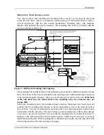
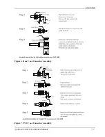
Once the cable assemblies have been made, attach the 15 and 37 pin d-sub and coaxial cable
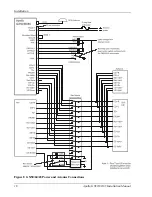
connectors to the rear connector mounting plate and the mounting frame as illustrated in Figure 4
and Figure 5. Route the wiring bundle as appropriate. The rear connector plate should be attached
to the mounting frame before installing the frame in the instrument panel. The rear connector
plate can be used to tie down the cable assemblies. Use the supplied edge guard to protect the
cable from sharp edges. Connect the shield grounds directly to the connector mounting plate.
Once the cable assemblies, the connector mounting plate, and the mounting frame are
assembled, install the mounting frame assembly in the instrument panel as illustrated in
Figure 3. Be sure to use low profile head screws so the unit will slide in and out freely. Attach
the front of the mounting frame to the instrument panel. Use support brackets to attach the
rear of the frame to the aircraft.
Summary of Contents for APOLLO GX60
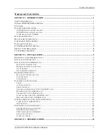
Page 4: ...NOTES ...
Page 8: ...Table of Contents iv Apollo GX50 60 65 Installation Manual NOTES ...
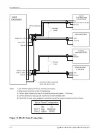
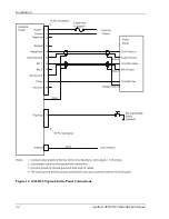
Page 30: ...Installation 22 Apollo GX50 60 65 Installation Manual Figure 12 RS 232 Serial Connections ...
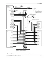
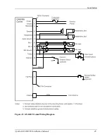
Page 31: ...Installation Apollo GX50 60 65 Installation Manual 23 Figure 13 GX60 65 Comm Wiring Diagram ...
Page 40: ...Installation 32 Apollo GX50 60 65 Installation Manual NOTES ...
Page 50: ...Limitations 42 Apollo GX50 60 65 Installation Manual NOTES ...
Page 54: ...Periodic Maintenance 46 Apollo GX50 60 65 Installation Manual NOTES ...
Page 82: ...Serial Interface Specifications 74 Apollo GX50 60 65 Installation Manual NOTES ...
Page 84: ...Full Stack Drawing 76 Apollo GX50 60 65 Installation Manual ...
Page 85: ......
Page 86: ......


