Installation
Apollo GX50/60/65 Installation Manual
19
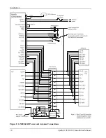
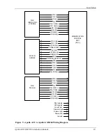
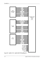
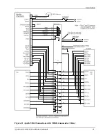
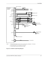
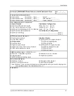
Figure 9 - Apollo ACU to Apollo GX50/60 Wiring Diagram
NAV
INDICATOR
(CDI/HSI)
APOLLO
GX50/60
NAV
Receiver
ANNUNCIATION
CONTROL
UNIT
(ACU)
CDI+R
27
From+
CDI+L
To+
NAV Valid(+)
NAV Valid(-)
GS +Up
VDI Valid(+)
ACTIVE
APPROACH
OBS/HOLD
MSG
GPS/SEQ(Obs/Hold)
PTK
CDI+L
CDI+R
From+
To+
Nav Valid(+)
VDI/Nav Valid(-)
CDI+L
CDI+R
GS+Up
From+
To+
Nav Valid (+)
GS Valid (+)
26
14
15
20
21
32
42
8
12
9
10
13
11
30
31
18
19
24
25
29
16
17
22
28
34
35
Power(Vcc)
Ground
78
1
15
33
34
16
26
17
14
13
11
12
10
29
40
VDI (-)Dn
VDI (+)Up
30
31
28
36
37
GS+Dn
GS Valid(+)
GS Valid(-)
33
38
39
GS Valid(-)
Nav Valid(-)
GS+Dn
23
41
Dimmer High
Dimmer Low
43
44
6
Lamp Test
5
4
GPS enable
NAV enable
Summary of Contents for APOLLO GX60
Page 4: ...NOTES ...
Page 8: ...Table of Contents iv Apollo GX50 60 65 Installation Manual NOTES ...
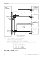
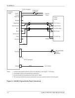
Page 30: ...Installation 22 Apollo GX50 60 65 Installation Manual Figure 12 RS 232 Serial Connections ...
Page 31: ...Installation Apollo GX50 60 65 Installation Manual 23 Figure 13 GX60 65 Comm Wiring Diagram ...
Page 40: ...Installation 32 Apollo GX50 60 65 Installation Manual NOTES ...
Page 50: ...Limitations 42 Apollo GX50 60 65 Installation Manual NOTES ...
Page 54: ...Periodic Maintenance 46 Apollo GX50 60 65 Installation Manual NOTES ...
Page 82: ...Serial Interface Specifications 74 Apollo GX50 60 65 Installation Manual NOTES ...
Page 84: ...Full Stack Drawing 76 Apollo GX50 60 65 Installation Manual ...
Page 85: ......
Page 86: ......

