


Installation
Apollo GX50/60/65 Installation Manual
25
P
OST
I
NSTALLATION
C
HECKOUT
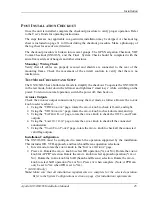
Once the unit is installed, complete the checkout procedure to verify proper operation. Refer
to the User’s Guide for operating instructions.
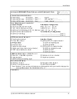
The steps that are not applicable to a particular installation may be skipped. A checkout log
sheet is included on page 31 to fill out during the checkout procedure. Make a photocopy of
the log sheet for ease of use if desired.
The checkout procedure is broken into several groups. The GPS Navigation Checkout, VHF
Comm Checkout (GX60/65), and the Final System Check should be completed with the
aircraft moved clear of hangers and other structures.
Mounting / Wiring Check
Verify that all cables are properly secured and shields are connected to the rear of the
mounting frame. Check the movement of the aircraft controls to verify that there is no
interference.
T
EST
M
ODE
C
HECKOUT AND
S
ETUP
The GX50/60/65 has a built-in test mode to simplify the checkout. To operate the GX50/60/65
in the test mode, hold down the leftmost and rightmost “smart keys” while switching on the
power. To return to normal operation, switch the power off, then back on.
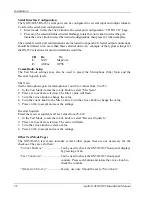
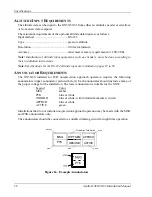
Avionics Outputs
Check the avionics output connections by using the test mode as follows. Rotate the
LARGE
knob to select each test.
1.
Using the “CDI
T
RIANGLE
” page, rotate the
SMALL
knob to check left, mid, and right.
2.
Using the “VDI
T
RIANGLE
” page, rotate the
SMALL
knob to check down, mid, and up.
3.
Using the “T
O
/F
ROM
F
LAG
” page, rotate the
SMALL
knob to check the Off, To, and From
outputs.
4.
Using the “L
AMP
O
UTPUTS
” page, rotate the
SMALL
knob to check all the connected
annunciators.
5.
Using the “V
ALID
F
LAG
P
AGES
” page, rotate the
SMALL
knob to check all the connected
valid flag outputs.
Installation Configuration
The GX50/60/65 must be configured to match the operation supported by the installation.
This includes IFR, VFR, approach, and Search and Rescue operation selections.
1.
In test mode, rotate the
LARGE
knob to the “I
NSTALL
O
PTIONS
” page.
2.
Press
SEL
. Rotate the
SMALL
knob to select IFR operation (Y
ES
or N
O
). Rotate the
LARGE
knob for APPR* selection. Rotate the
SMALL
knob to select approach operation (Y
ES
or
N
O
). Rotate the
LARGE
knob for SAR (Search and Rescue) selection. Rotate the
SMALL
knob to select SAR operation (Y
ES
or N
O
). Press
ENT
when complete. (Note: APPR can
only be set to Y
ES
when IFR is set to Y
ES
).
*
(GX50/60 only)
Note:
Make sure that all installation requirements are complete for the selected operation.
Refer to the System Configurations section on page 4 for installation requirements.
Summary of Contents for APOLLO GX60
Page 4: ...NOTES ...
Page 8: ...Table of Contents iv Apollo GX50 60 65 Installation Manual NOTES ...
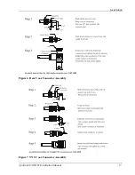
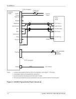
Page 30: ...Installation 22 Apollo GX50 60 65 Installation Manual Figure 12 RS 232 Serial Connections ...
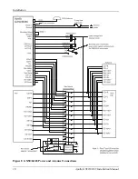
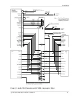
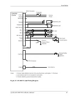
Page 31: ...Installation Apollo GX50 60 65 Installation Manual 23 Figure 13 GX60 65 Comm Wiring Diagram ...
Page 40: ...Installation 32 Apollo GX50 60 65 Installation Manual NOTES ...
Page 50: ...Limitations 42 Apollo GX50 60 65 Installation Manual NOTES ...
Page 54: ...Periodic Maintenance 46 Apollo GX50 60 65 Installation Manual NOTES ...
Page 82: ...Serial Interface Specifications 74 Apollo GX50 60 65 Installation Manual NOTES ...
Page 84: ...Full Stack Drawing 76 Apollo GX50 60 65 Installation Manual ...
Page 85: ......
Page 86: ......