


Specifications
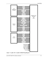
Apollo GX50/60/65 Installation Manual
33
S
ECTION
3
-
S
PECIFICATIONS
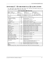
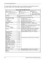
This section includes detailed electrical, physical, environmental, and performance
specifications for the Apollo GX50 and GX60/65.
E
LECTRICAL
Input voltage............................................. 10VDC to 40VDC, reverse polarity protected
Input current (GPS navigation input) ....... 500 mA typical, 750 mA max. at 13.75 VDC
250 mA typical, 375 mA max. at 27.5 VDC
Input current (comm input) ...................... 270 mA typical, 2A max. at 13.75 VDC, receive
130 mA typical, 900 mA max. at 27.5 VDC, receive
2.1 A typical, 3.2 A max. at 13.75 VDC, transmit
1.0 A typical, 1.4 A max. at 27.5 VDC, transmit
Note:
Receive max. at full receive audio, transmit
max. at 90% modulation at 1000 Hz
Input power (GPS navigation input)......... 7 watts typical
Input power (comm input)........................ 3.7 watts typical, receive
28 watts typical, transmit
Internal fuses ............................................ Nav input: 3 amp fast blow, surface mount on-board
Comm input : 7 amp fast blow, soldered in-board
Fuses must be replaced with the same or equivalent
type (contact the factory).
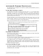
Memory backup........................................ Internal lithium battery with a service life of
approximately 4 to 6 years. See Appendix B for
battery replacement instructions.
Note:
The GX50/60/65 will provide a message on the display when the Lithium battery is
running low and needs replacement.
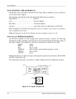
P
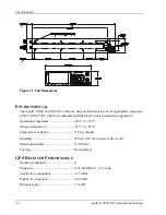
HYSICAL
Height ....................................................... 2.00 inches (5.08 cm)
Width........................................................ 6.25 inches (15.88 cm)
Depth ........................................................ 11.45 inches (29.1 cm) behind panel, including
mounting frame and connectors
Weight (with mounting frame)................. GX50: 2.6 lb. (1.179 kg)
GX60/65: 3.1 lb. (1.409 kg)
Summary of Contents for APOLLO GX60
Page 4: ...NOTES ...
Page 8: ...Table of Contents iv Apollo GX50 60 65 Installation Manual NOTES ...
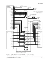
Page 30: ...Installation 22 Apollo GX50 60 65 Installation Manual Figure 12 RS 232 Serial Connections ...
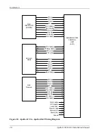
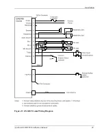
Page 31: ...Installation Apollo GX50 60 65 Installation Manual 23 Figure 13 GX60 65 Comm Wiring Diagram ...
Page 40: ...Installation 32 Apollo GX50 60 65 Installation Manual NOTES ...
Page 50: ...Limitations 42 Apollo GX50 60 65 Installation Manual NOTES ...
Page 54: ...Periodic Maintenance 46 Apollo GX50 60 65 Installation Manual NOTES ...
Page 82: ...Serial Interface Specifications 74 Apollo GX50 60 65 Installation Manual NOTES ...
Page 84: ...Full Stack Drawing 76 Apollo GX50 60 65 Installation Manual ...
Page 85: ......
Page 86: ......