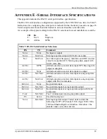
Serial Interface Specifications
68
Apollo GX50/60/65 Installation Manual
F
UEL
/A
IR
D
ATA
C
OMPUTER
I
NPUT
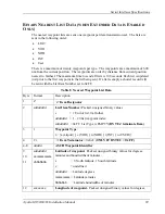
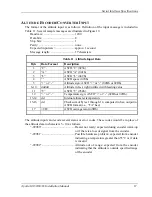
The fuel/air data input is used to input fuel flow and airdata computer information from the
fuel/air data computer. See Table 5, or contact Customer Service, for appropriate devices.
“S”
D
ATA
F
ORMAT
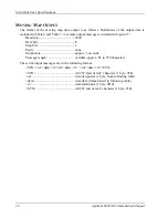
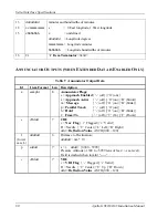
The format of the fuel/air data computer input is as follows, which conforms to the Shadin
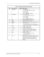
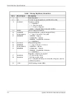
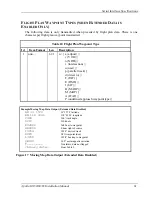
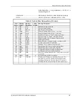
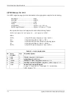
“S” format serial message. Definition of the input message data that the GX50/60/65 uses is
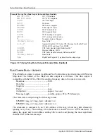
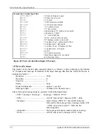
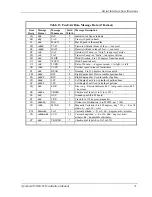
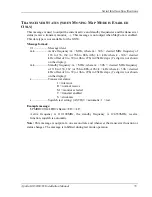
included in Table 12. A sample input message is illustrated in Figure 20.
Baud rate: ..........................................9600
Data bits: ...........................................8
Stop bits: ...........................................1
Parity: ................................................none
Expected input rate: ..........................approx. 1 second
Message length: ................................variable (512 character max.)
The serial input message string is expected in the following format.
<STX><message><message> ... <message><chksum><ETX>
<STX> ...............................................ASCII “start of text” character (STX = 02h)
<message> .........................................starts with an ASCII “S”, then an ID character,
followed by the message data, a carriage return (CR
= 0Dh), and a line feed (LF = 0Ah) See the
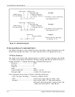
Altitude Sign Altitude in Feet
Temperature Sign
Example 1
Altitude Encoder/ Internal Temperature
Converter Identifier Message Checksum
210 feet above sea level (@29.92 gh)
#AL +25D4
with temperature of 25
°
C
Altitude Sign Altitude in Feet
Temperature Sign
Example 2
Altitude Encoder/ Internal Temperature
Converter Identifier Message Checksum
45 feet below sea level (@29.92 gh)
#AL -45DE
with temperature of 45
°
C
Status Code
Example 3
Message Checksum
Indicates encoder is warming up
#AL -12E9
(is still below +25
°
C)
Figure 19 Altitude Data Input
Summary of Contents for APOLLO GX60
Page 4: ...NOTES ...
Page 8: ...Table of Contents iv Apollo GX50 60 65 Installation Manual NOTES ...
Page 30: ...Installation 22 Apollo GX50 60 65 Installation Manual Figure 12 RS 232 Serial Connections ...
Page 31: ...Installation Apollo GX50 60 65 Installation Manual 23 Figure 13 GX60 65 Comm Wiring Diagram ...
Page 40: ...Installation 32 Apollo GX50 60 65 Installation Manual NOTES ...
Page 50: ...Limitations 42 Apollo GX50 60 65 Installation Manual NOTES ...
Page 54: ...Periodic Maintenance 46 Apollo GX50 60 65 Installation Manual NOTES ...
Page 82: ...Serial Interface Specifications 74 Apollo GX50 60 65 Installation Manual NOTES ...
Page 84: ...Full Stack Drawing 76 Apollo GX50 60 65 Installation Manual ...
Page 85: ......
Page 86: ......


