Serial Interface Specifications
Apollo GX50/60/65 Installation Manual
69
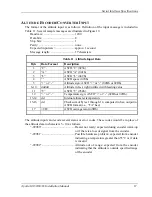
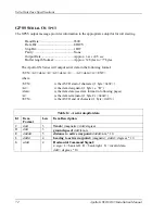
following table. s = a sign indicator (-,+,E,W). d = a
decimal digit (0-9)
<checksum> ...................................... the message checksum, same format as message
<ETX> .............................................. ASCII “end of text” character (ETX = 03h)
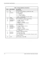
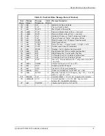
Table 12 Fuel/Air Data Message Data (S Format)
Item
Desig
Message
Format
Message
Mnemonic
Field
Width
Message Description
SA
ddd
IAS
7
Indicated Air Speed in knots
SB
ddd
TAS
7
True Air Speed in knots
SC
ddd
MACH
7
Mach Speed in thousandths
SD
sdddd
PALT
9
Pressure Altitude in tens of feet, +/- sea level
SE
sdddd
DALT
9
Density Altitude in tens of feet, +/- sea level
SF
sdd
OAT
7
Outside Air Temp - or “Total”, in degrees Celsius
SG
sdd
TAT
7
True Air Temp - or “Static”, in degrees Celsius
SH
ddd
WDIR
7
Wind Direction, 0 to 359 degrees from true north
SI
ddd
WSPD
7
Wind Speed in knots
SJ
sdd
TURN
7
Rate of Turn in +/- degrees/second, + is right, - is left
SK
sddd
VSPD
8
Vertical speed in tens of feet/minute
SL
ddd
HEAD
7
Heading, 0 to 359 degrees from true north
SM
dddd
RFF
8
Right Engine Fuel Flow in tenths of gallons/hour
SN
ddddd
RFU
9
Right Engine Fuel Used in tenths of gallons
SO
dddd
LFF
8
Left Engine Fuel Flow in tenths of gallons/hour
SP
ddddd
LFU
9
Left Engine Fuel Used in tenths of gallons
SQ
ddd
ERR
7
Error Log / Reason Indicator: 001 = temp sensor error; 000
= no errors
SR
ddddd
REM
10
Fuel remaining (0-9999.9 in gallons)
S*
ddd
CKSUM
7
Checksum of all characters preceding this record. The
checksum is a one byte checksum (discarding carries)
including all characters from the initial STX up to and
including the line feed preceding the checksum message.
Summary of Contents for APOLLO GX60
Page 4: ...NOTES ...
Page 8: ...Table of Contents iv Apollo GX50 60 65 Installation Manual NOTES ...
Page 30: ...Installation 22 Apollo GX50 60 65 Installation Manual Figure 12 RS 232 Serial Connections ...
Page 31: ...Installation Apollo GX50 60 65 Installation Manual 23 Figure 13 GX60 65 Comm Wiring Diagram ...
Page 40: ...Installation 32 Apollo GX50 60 65 Installation Manual NOTES ...
Page 50: ...Limitations 42 Apollo GX50 60 65 Installation Manual NOTES ...
Page 54: ...Periodic Maintenance 46 Apollo GX50 60 65 Installation Manual NOTES ...
Page 82: ...Serial Interface Specifications 74 Apollo GX50 60 65 Installation Manual NOTES ...
Page 84: ...Full Stack Drawing 76 Apollo GX50 60 65 Installation Manual ...
Page 85: ......
Page 86: ......

