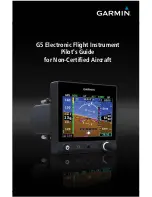
background image

G5 Electronic Flight Instrument 

Pilot's Guide 

for Non-Certified Aircraft 

Summary of Contents for Approach G5 - GPS-Enabled Golf Handheld

Page 1: ...G5 Electronic Flight Instrument Pilot s Guide for Non Certified Aircraft...

Page 2: ...Blank Page...

Page 3: ...SYSTEM OVERVIEW FLIGHT INSTRUMENTS AFCS ADDITIONAL FEATURES INDEX...

Page 4: ...Blank Page...

Page 5: ...erein no part of this manual may be reproduced copied transmitted disseminated downloaded or stored in any storage medium for any purpose without the express written permission of Garmin Garmin hereby...

Page 6: ...dealer or the Garmin website Contact your local waste disposal department to dispose of the device and battery in accordance with applicable local laws and regulations WARNING To reduce the risk of u...

Page 7: ...CTIVE COATING It is very important to clean the lens using a clean lint free cloth and a cleaner that is specified as safe for anti reflective coatings Avoid any chemical cleaners or solvents that can...

Page 8: ...unlikely it may be possible for erroneous operation to occur without a fault indication shown by the G5 It is thus the responsibility of the pilot to detect such an occurrence by means of cross checki...

Page 9: ...dio communications However there is no guarantee that interference will not occur in a particular installation If this equipment does cause harmful interference to radio or television reception which...

Page 10: ...ased newly overhauled products 6 months or 200 flight hours for factory repaired or newly overhauled products exchanged through a Garmin Authorized Service Center Within the applicable period Garmin w...

Page 11: ...tion SUCH REMEDY SHALL BE YOUR SOLE AND EXCLUSIVE REMEDY FOR ANY BREACH OF WARRANTY Online Auction Purchases Products purchased through online auctions are not eligible for warranty coverage Online au...

Page 12: ...pdates D December 2016 Added autopilot trim and speed annunciations E May 2017 Added GMU 11 info various updates F June 2017 Added Declaration of Conformity for RED compliance G October 2017 Removed I...

Page 13: ...19 2 1 6 Vertical Speed Indicator VSI 21 2 1 7 PFD Pitch Attitude Offset 22 2 1 8 Battery Status Indicator 23 2 2 HSI Page 24 2 2 1 Horizontal Situation Indicator HSI 25 2 2 2 Heading Ground Track HS...

Page 14: ...Flight Director Operation 47 3 1 13 Vertical Modes 52 3 1 14 Lateral Modes 63 3 2 System Messages 71 3 3 AFCS Alerts Optional 72 3 3 1 Status Alerts 72 3 3 2 Speed Alerts 72 Section 4 Additional Featu...

Page 15: ...G5 Electronic Flight Instrument Pilot s Guide for Non Certified Aircraft 190 02072 00 Rev G iii Table of Contents...

Page 16: ...G5 Electronic Flight Instrument Pilot s Guide for Non Certified Aircraft 190 02072 00 Rev G iv Table of Contents Blank Page...

Page 17: ...When installed as part of a G3X system the G5 provides a redundant source of attitude and air data to the G3X displays and additionally provides backup autopilot control allowing coupled GPS approach...

Page 18: ...he barometric setting From the HSI Page rotate to adjust the heading or track bug Turn to select the desired value when editing numeric data or selecting from a list 1 2 micro SD CARDS The G5 data car...

Page 19: ...not likely an installation related problem the G5 should be serviced by a Garmin authorized repair facility Figure 1 2 G5 Failure Annunciations 1 4 2 G5 ATTITUDE The G5 calculates aircraft attitude us...

Page 20: ...l that describes the Earth s main magnetic field and its annual rate of change The database is updated approximately every 5 years via a software update Failure to update this database could lead to e...

Page 21: ...efer to the Installation Manual section for more information The G5 has two main pages the HSI Page and the PFD Page The HSI Page can be accessed from the PFD Page unless it has been disabled in confi...

Page 22: ...02072 00 Rev G 10 System Overview System Overview Flight Instruments AFCS Additional Features Index 1 5 2 MENU Press the Knob to access the G5 Menu Navigate the menu by rotating the Knob and make sele...

Page 23: ...l Features Index Section 2 FLIGHT INSTRUMENTS 2 1 PFD PAGE The G5 PFD Page displays a horizon airspeed attitude altitude vertical speed heading and course deviation information The following flight in...

Page 24: ...ery Status Indicator 2 1 1 AIRSPEED INDICATOR NOTE The G5 Vspeed Reference values depend upon the aircraft s specific system configuration and may vary from the examples discussed in this sec tion The...

Page 25: ...rspeed is not available due to a system failure Figure 2 2 Airspeed Indicator Ground Speed Actual Airspeed Airspeed Trend Vector Airspeed Color Ranges Vspeed References 2 1 1 1 VNE ADJUSTED FOR TRUE A...

Page 26: ...references includingVNE Vno Vso Vs1 Vfe Va Vx Vy VYse Vg Vr can be configured to display on the G5 refer to the Installation Manual section for more information When airspeed is present the Vspeeds c...

Page 27: ...all pitch ranges Refer to the Installation Manual section to configure the pitch scale The inverted white triangle indicates zero on the roll scale Major tick marks at 30 and 60 and minor tick marks a...

Page 28: ...ual for configuration information The Ground Pointer configuration displays both the roll arc and the pitch ladder anchored to the horizon and the roll pointer beneath the roll arc pointing to the pre...

Page 29: ...a selection bug symbol A bug corresponding to this altitude is shown on the tape if the Selected Altitude exceeds the range shown on the tape the bug appears at the corresponding edge of the tape The...

Page 30: ...ng function provides the pilot with a visual alert when approaching the Selected Altitude Whenever the Selected Altitude is changed the Altitude Alerter is reset The following will occur when approach...

Page 31: ...n on the indicator by the trend vector stopping at the standard turn rate tick mark Figure 2 11 Turn Rate Indicator Turn Rate Indicator Standard Rate Tick Marks Turn Rate Trend Vector 2 1 5 HEADING GR...

Page 32: ...5 and the other displays in a G3X G3X Touch system Adjusting the selected heading or ground track Use the HDG Knob on the GMC 307 Or 1 Press the Knob to display the Menu 2 Select Heading or Track and...

Page 33: ...CAL SPEED INDICATOR VSI The Vertical Speed Indicator displays the aircraft vertical speed using a non moving tape with minor tick marks every 100 feet The current vertical speed is displayed using a w...

Page 34: ...down much like the aircraft on a mechanical attitude indicator The pitch attitude can be adjusted as much as 5 The pitch offset is synchronized between the G5 and the other displays in a G3X G3XTouch...

Page 35: ...powered by the battery the estimated time until the battery is empty is displayed Otherwise the current charge level of the battery in percent is displayed as a numeric value When the G5 is connected...

Page 36: ...in configuration mode Figure 2 16 Horizontal Situation Indicator HSI 8 7 2 4 5 3 1 Distance To Waypoint 2 Battery Status Indicator 3 Navigation Source 4 Aircraft Symbol 5 Navigator Messages 6 Rotating...

Page 37: ...al NOTE The VFR CDI Scale is displayed when the G5 is connected to a GPS navigator via RS 232 only or ifARINC 429 GPS navigation data is unavailable 2 2 1 HORIZONTAL SITUATION INDICATOR HSI The Horizo...

Page 38: ...bearing pointer is light blue The bearing pointer never overrides the CDI and is visually separated from the CDI by a white ring shown when the bearing pointer is selected but not necessarily visible...

Page 39: ...t or right from the course pointer along a lateral deviation scale to display aircraft position relative to the course If the course deviation data is not valid the CDI is not displayed The CDI is cap...

Page 40: ...corresponds to the Selected Heading or Ground Track NOTE Heading is displayed if magnetometer data is available from a mag netometer via the CAN network Otherwise Ground Track is displayed Adjusting...

Page 41: ...plays navigation data from the external navigator selected on the G3X PFD Navigation data from the G3X internal flight plan is not displayed on the G5 If multiple navigation sources are configured and...

Page 42: ...to the course If the course deviation data is not valid the CDI is not displayed The CDI is capable of displaying multiple sources of navigation GPS VLOC or both depending on the external navigator s...

Page 43: ...toggle between GPS and VOR LOC source types Refer to the appropriate external navigator Pilot s Guide for more information Changing the navigation source on the G5 GPS VOR LOC or VLOC Refer to the G5...

Page 44: ...ERTICAL DEVIATION INDICATOR AND VNAV INDICATOR NOTE An external navigator i e GTN GNS GNC 255 or SL30 Nav Comm Transceiver must be configured to receive glideslope and or glidepath vertical deviation...

Page 45: ...tion Glideslope Indicator VDI appears to the left of the altimeter whenever an ILS frequency is tuned in the active NAV field of an external navigator A green diamond acts as the VDI Indicator like a...

Page 46: ...r VDI also appears to the left of the altimeter during a GPS approach The glidepath is analogous to the glideslope for GPS approaches supporting WAAS vertical guidance LNAV V L VNAV LPV The Glidepath...

Page 47: ...ght Instruments AFCS Additional Features Index 2 3 2 3 VNAV INDICATOR NOTE VNAV deviation is only displayed when the G5 is receiving NMEA RS 232 data from a portable GPS The magenta chevron VNAV Indic...

Page 48: ...ON When the G5 is receivingVOR LOC or GPS data a Course menu option is displayed Setting the course for a VOR or localizer 1 From the PFD Page press the Knob to display the Menu 2 Select Course and us...

Page 49: ...d roll commands are displayed on the PFD Page as Command Bars When the Flight Director is active the pitch and roll commands can be hand flown by the pilot or when coupled with the autopilot the autop...

Page 50: ...ch axis uses pitch rate to stabilize the aircraft pitch attitude during flight director maneuvers Flight director pitch commands are rate and attitude limited combined with pitch damper control and se...

Page 51: ...ng Control Wheel Steering The green AP annunciation is temporarily replaced by a white CW for the duration of Control Wheel Steering maneuvers In most scenarios releasing the CWS Button reengages the...

Page 52: ...The G5 supports the following modes LVL PIT ROL HDG TRK GPS VS IAS ALT ALTS TO GA and GP GP mode requires ARINC 429 data from an IFR navigator TRK mode is selected using the HDG Button on the GMC and...

Page 53: ...al electric trim may provide trim capability for any properly configured axis pitch roll or yaw when the autopilot is not engaged NOTE Refer to the G5 Installation Manual Section for information on in...

Page 54: ...modes 5 NOSE UP DN Wheel Adjusts the vertical mode reference in Pitch Hold Vertical Speed Indicated Airspeed and Altitude Hold modes 6 IAS Key Selects deselects Indicated Airspeed Mode 7 ALT Key Sele...

Page 55: ...rtified Aircraft 190 02072 00 Rev G 43 AFCS System Overview Flight Instruments AFCS Additional Features Index 1 2 3 4 5 6 7 8 10 9 12 11 Figure 3 2 GMC 305 AFCS Control Unit Active Mode 13 12 3 4 5 14...

Page 56: ...temporarily disengage the pitch and roll servos and interrupt autotrim operation The pilot can then hand fly the aircraft to a new attitude and release the AP DISC CWS button to re engage the autopil...

Page 57: ...l Modes Selected Lateral Vertical Mode Annunciation Mode Annunciation CWS Button if equipped press and hold Roll Hold ROL Pitch Hold PIT HDG Heading HDG Pitch Hold PIT NAV Navigation GPS Pitch Hold PI...

Page 58: ...System failure Invalid sensor data Inability to compute default autopilot modes Detection of a GDU display on the CAN network when installed as part of a G3X G3X Touch system 3 1 11 3 1 Disengaging th...

Page 59: ...utomatic trim to run resulting in an out of trim condition or cause the trim to hit the stop if the action is prolonged In this case larger than anticipated control forces may be required after the au...

Page 60: ...ROL Pitch Hold default PIT TO GA Button Takeoff on ground Go Around in air TO GA Takeoff on ground Go Around in air TO GA ALT Key Roll Hold default ROL Altitude Hold ALT VS Key Roll Hold default ROL...

Page 61: ...ive mode is indicated by the white armed mode annunciation moving to the green active mode field and flashing for 10 seconds If the information required to compute a flight director mode becomes inval...

Page 62: ...e displayed hollow The Command Bars do not override the Aircraft Symbol The Command Bars move together vertically to indicate pitch commands and bank left or right to indicate roll commands Hollow Com...

Page 63: ...following two options are available Normal The Flight Director enters Altitude Hold ALT Mode Sync Selected Altitude The Flight Director enters Altitude Hold ALT Mode and the Selected Altitude Altitude...

Page 64: ...st the target vertical speed to a value that would cause the aircraft to fly away from the Selected Altitude Unlike Select VS Mode described previously this option does not switch to VS mode Instead i...

Page 65: ...speed IAS Maintains the current aircraft airspeed in IAS while the aircraft is climbing descending to the Selected Altitude IAS Key IAS 1 kt Vertical Navigation Captures and tracks descent legs of an...

Page 66: ...h Hold Mode is activated In Pitch Hold Mode the flight director maintains a constant pitch attitude The pitch reference is set to the aircraft pitch attitude at the moment of mode selection If the air...

Page 67: ...nsition is indicated by the green ALTS annunciation flashing for up to 10 seconds and the appearance of the white ALTS annunciation At 50 feet from the Selected Altitude the flight director automatica...

Page 68: ...tically transitions to Altitude Hold Mode when within 50 feet of the Selected Altitude In this case the Selected Altitude becomes the Altitude Reference 3 1 13 3 1 Changing the Altitude Reference When...

Page 69: ...d Mode activation This mode may be used for climb or descent to the Selected Altitude shown above the Altimeter since Selected Altitude Capture Mode is automatically armed when Vertical Speed Mode is...

Page 70: ...Vertical Speed Mode Active 3 1 13 5 INDICATED AIRSPEED MODE IAS Indicated Airspeed Mode is selected by pressing the IAS Key on the GMC This mode acquires and maintains the Airspeed Reference IAS while...

Page 71: ...PFD Page Indicated Airspeed Reference Bug Indicated Airspeed Reference 3 1 13 6 VERTICAL NAVIGATION MODE VNV NOTE If another vertical mode is touched while VNV Mode is selected VNV Mode reverts to ar...

Page 72: ...altimeter s barometric setting is adjusted while VNV mode is active the autopilot increases decreases the descent rate by up to 500 fpm to re establish the aircraft on the descent path without comman...

Page 73: ...GPS approaches provide a vertical descent angle as an aid in flying a stabilized approach These approaches are NOT considered Approaches withVertical Guidance APV Approaches that are annunciated on th...

Page 74: ...gs level The GA Switch is used to activate both modes The mode entered by the flight director depends on whether the aircraft is on the ground or in the air Takeoff Mode provides an attitude reference...

Page 75: ...ings level depending on the commanded bank angle default ROL Heading Installations with a magnetometer Captures and tracks the Selected Heading HDG Key HDG Track Installations without a magnetometer C...

Page 76: ...olls the wings level When the flight director is activated or switched Roll Hold Mode is selected by default This mode is annunciated as ROL in the Autopilot Status Box The current aircraft bank angle...

Page 77: ...blue bug on the HSI and in the box on the bottom right of the HSI Changing the selected heading 1 Press the Knob to display the Menu 2 Select Heading and use the Knob to change the Selected Heading Or...

Page 78: ...ed ground track 1 Press the Knob to display the Menu 2 Select Track and use the Knob to change the Selected Ground Track Or Rotate the HDG Knob on the GMC Activating track mode Press the HDG Key on th...

Page 79: ...ation Mode Navigation Mode acquires and tracks the navigation source The flight director follows GPS roll steering commands when GPS is the navigation source Navigation Mode can also be used to fly no...

Page 80: ...eviation is less than one dot to activate capture and track the selected navigation source Table 3 8 Approach without Vertical Guidance Example Control Lateral Mode Annunciation Description LNAV NAV K...

Page 81: ...ateral Vertical Approaches Example Control Modes Annunciation Description LPV LNAV VNAV LNAV V APR Key Lateral GPS GPS Captures and tracks the lateral portion of a GPS approach Vertical Glidepath GP C...

Page 82: ...es and is annunciated as both the vertical and lateral modes when active Pressing the LVL Key engages the autopilot in Level vertical and lateral modes Level Mode does not track altitude or heading Wh...

Page 83: ...fault Unit has a hardware fault contact Garmin for service Power supply fault Unit power supply fault detected contact Garmin for service if it persists Unit temperature limit exceeded Unit is too hot...

Page 84: ...ired TRIM UP The autopilot does not have the required elevator authority to reach the desired flight condition Down elevator Trim Required TRIM DOWN Table 3 11 Status Alerts 3 3 2 SPEED ALERTS If the...

Page 85: ...use the aircraft to exceed the normal or protected flight envelope This is perceived by the pilot as resistance to control movement in the undesired direction when the aircraft approaches a steep atti...

Page 86: ...terrain data is unavailable automatic engagement of Level mode is not supported ESP is enabled or disabled from the PFD Page Menu Enabling Disabling ESP using the G3X Touch Autopilot Interface 1 From...

Page 87: ...ere ESP will engage As roll attitude exceeds the configured limit ESP will engage and the Roll Limit Indicators will move to 15 less than the configured ESP bank limit The Roll Limit Indicator now ind...

Page 88: ...e Increases as Roll Increases Decreases as Roll Decreases 0 10 10 20 20 30 30 4 5 45 6 0 6 0 7 5 7 5 90 90 Configured Bank Limit 45 Minimum ESP Torque 30 Maximum ESP Torque 60 Maximum ESP Torque 60 Mi...

Page 89: ...of yellow chevrons indicate that ESP is engaged in these nose up nose down conditions Figure 4 5 ESP Engaged Nose Low Figure 4 6 ESP Engaged Nose High Figure 4 7 ESP Pitch Operating Range When Engage...

Page 90: ...TE If AGL height data is unavailable i e GPS altitude or terrain data is unavailable low airspeed protection is not supported An airspeed below the minimum configured airspeed or above maximum configu...

Page 91: ...26 C Command Bars 50 Control Wheel Steering CWS 39 D Display Overview 5 F Flight director FD 40 Modes vertical 52 66 Flight Level Change Mode 58 G Glidepath Mode GP 61 H Heading 12 Heading Select Mode...

Page 92: ...rcraft 190 02072 00 Rev G Index Index 2 System Overview Flight Instruments AFCS Additional Features Index T Takeoff Mode 62 Transponder Status Box 12 True Airspeed TAS 12 V Vertical Deviation Indicato...

Page 93: ...G5 Electronic Flight Instrument Pilot s Guide for Non Certified Aircraft 190 02072 00 Rev G Blank Page...

Page 94: ...SE Salem OR 97302 U S A Garmin Europe Ltd Liberty House Hounsdown Business Park Southampton Hampshire SO40 9LR U K Garmin Corporation No 68 Zhangshu 2nd Road Xizhi District New Taipei City Taiwan Con...

Reviews: