


Garmin G5 User's Manual
190-02072-00 Rev. B
9
Installation Manual
Installation Manual
Pilot's Guide
Index
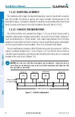
The following items should be considered when installing/removing/replacing LRUs
on the CAN bus:
1) CAN bus node connections must be made on the connector of each LRU
that connects to the CAN bus, do not tie CAN bus nodes from individual
LRUs together into a single connection point.
2) Keep all node lengths as short as practical.
3) If a G5 or GAD 29 (that was used as a CAN bus termination) is removed,
the CAN bus will remain terminated as long as the CAN bus terminator
(Figure 1-2) is left connected.
4) A removal adapter (011-03158-00) is provided (with each GSA 28
connector kit) that can be used when a GSA 28 is removed. The adapter
keeps that node on the CAN bus in the same state as when the servo was
connected (either terminated or un-terminated). The adapter also allows
trim signals to pass through when the servo is removed.
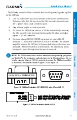
NOTE:
The 120
Ω
termination resistors described in the preceding paragraphs
are “built-in” to the termination methods shown in the following figures. Do not
install a separate “discrete” 120
Ω
resistor to terminate the CAN bus in addition
to the termination methods shown in Figure 1-2 and Figure 1-3.
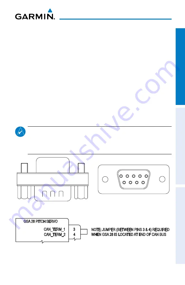
GARMIN CAN TERMINATOR
Figure 1-2 CAN Bus Termination (011-02887-00) for the G5 and GAD 29
NOTE: JUMPER (BETWEEN PINS 3 & 4) REQUIRED
WHEN GSA 28 IS LOCATED AT END OF CAN BUS
CAN_TERM_1 3
CAN_TERM_2 4
GSA 28 PITCH SERVO
Figure 1-3 CAN Bus Termination for the GSA 28