


Garmin G5 User's Manual
190-02072-00 Rev. B
10
Installation Manual
Installation Manual
Pilot's Guide
Index
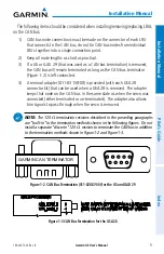
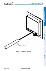
1.2.2.4 CABLE CONNECTOR INSTALLATION
A coaxial cable connection is required for the optional external GPS antenna.
1) Route the coaxial cable to the unit location. Secure the cable in accordance
with good aviation practices.
2) Trim the coaxial cable to the desired length and install the BNC connector.
If provided, follow the connector manufacturer’s instructions for cable
preparation.
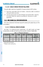
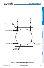
1.2.3 MECHANICAL CONSIDERATIONS
This section presents all information required for planning the physical layout of the
G5 installation.
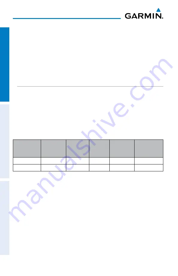
1.2.3.1 PHYSICAL SPECIFICATIONS
Use Table 1-4 to determine panel requirements. All width, height, and depth
measurements are taken with unit mounting ring and connectors (if applicable).
Table 1-4 G5 Physical Specifications
Configuration
Width
Height
Depth*
Unit Weight
Weight of
Unit and
Connector**
G5
3.42 in
3.60 in
2.61 in
0.55 lb
0.70 lb
G5 with Battery
3.42 in
3.60 in
3.03 in
0.83 lb
0.98 lb
*Depth behind aircraft panel
**Weight includes mounting ring