

Garmin G5 User's Manual
190-02072-00 Rev. B
13
Installation Manual
Installation Manual
Pilot's Guide
Index
1.3.2 GENERAL SPECIFICATIONS
See Section 1.2.1.1 for power/current specifications, and Section 1.2.3.1 for
dimension/weight specifications.
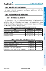
1.3.3 INSTALLATION INFORMATION
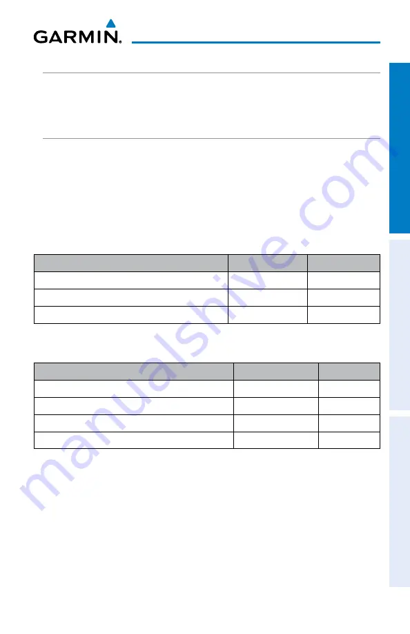
1.3.3.1 REQUIRED EQUIPMENT
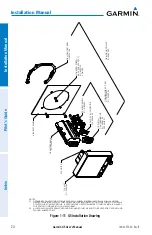
The installation kit (Table 1-5) is required to install the unit, one kit is required for
each G5 installed. The G5 Mounting Ring is included in the installation kit to mount
the G5 to the aircraft panel and to reinforce the panel cutout in thin panel installations.
The installation kit is not included with the G5.
Table 1-5 Contents of the G5 Installation Kit (011-03892-00)
Item
Garmin P/N
Quantity
Connector Kit, 9 Pin, w/CAN Term
011-03002-00
1
Mounting Ring, G5
115-02251-03
1
Screw, 6-32, 0.500"
211-60207-12
3
Table 1-6 Contents of the Connector Kit (011-03002-00)
Item
Garmin P/N
Quantity
Sub-Assy, Bkshl w/Hdw, Jackscrew, 9 pin
011-01855-00
1
Sub Assy, CAN Termination Kit
011-02887-00
1
Conn, Rcpt, D-Sub, Crimp Socket, 9 Ckt
330-00625-09
1
Contact, Sckt, D-Sub, Crimp, Size 20, 20-24 AWG
330-00022-02
9