Garmin G5 User's Manual
190-02072-00 Rev. B
38
Installation Manual
Installation Manual
Pilot's Guide
Index
1.7.4.2.1 G5 P
oSt
-i
nStaLLation
C
aLibration
P
roCedureS
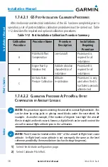
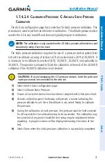
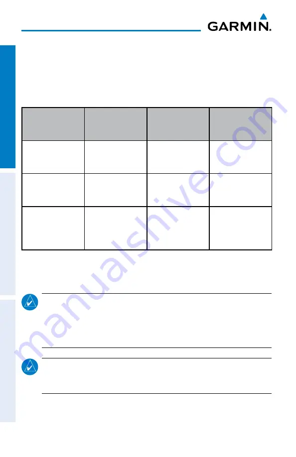
After mechanical and electrical installation of the G5 has been completed, prior to
operation, a set of post-installation calibration procedures must be carried out. Table
1-12 describes the required and optional calibration procedures.
Table 1-12 Post-Installation Calibration Procedure Summary
Calibration
Procedure
Procedure Name
Procedure
Description
Installations
Requiring
Procedure
A
Pitch/Roll Offset
Compensation
Level aircraft
Procedure A is
required for all
installations
B
Engine Run-Up
Vibration Test
Validate vibration
characteristics of
installation
Procedure B is
required for all
installations
C
Air Data Static
Pressure Calibration
Altitude
re-calibration
Procedure C is only
used when the G5
has failed a periodic
altimeter test
1.7.4.2.2 C
aLibration
P
roCedure
a: P
itCh
/r
oLL
o
ffSet
C
omPenSation
by
a
irCraft
L
eveLinG
NOTE:
This procedure requires orienting the aircraft to normal flight attitude. This
can be done by using jacks or placing wood blocks under the nose-wheel, for
example. As another example, if the number of degrees ‘nose high’ the aircraft
flies in straight and level cruise is known, a digital level can be used to orient the
aircraft to normal flight attitude prior to the calibration.
NOTE:
The G5 must be leveled within 30.0
°
of the aircraft in-flight level cruise
attitude. In-flight level cruise attitude is not necessarily the same as the level
reference provided by the manufacturer (such as fuselage longerons).
1)
Select the Attitude configuration page.
2)
Select Calibrate Pitch/Roll.