background image

G5 Install Manual &  
Pilot's Guide

Summary of Contents for Approach G5 - GPS-Enabled Golf Handheld

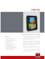
Page 1: ...G5 Install Manual Pilot s Guide ...

Page 2: ...Blank Page ...

Page 3: ...INSTALLATION MANUAL PILOT S GUIDE APPENDIX INDEX ...

Page 4: ...Blank Page ...

Page 5: ...ad Xizhi District New Taipei City Taiwan Tel 34 93 357 2608 Fax 34 93 429 4484 Web Site Address www garmin com Except as expressly provided herein no part of this manual may be reproduced copied transmitted disseminated downloaded or stored in any storage medium for any purpose without the express written permission of Garmin Garmin hereby grants permission to download a single copy of this manual...

Page 6: ...armin website Contact your local waste disposal department to dispose of the device and battery in accordance with applicable local laws and regulations WARNING To reduce the risk of unsafe operation carefully review and understand all aspects of the G5 Install Manual Pilot s Guide documentation and the Pilot s Operating Handbook of the aircraft Thoroughly practice basic operation prior to actual ...

Page 7: ... is very important to clean the lens using a clean lint free cloth and a cleaner that is specified as safe for anti reflective coatings Avoid any chemical cleaners or solvents that can damage plastic components CAUTION The G5 does not contain any user serviceable parts Repairs should only be made by an authorized Garmin service center Unauthorized repairs or modifications could result in permanent...

Page 8: ...be possible for erroneous operation to occur without a fault indication shown by the G5 It is thus the responsibility of the pilot to detect such an occurrence by means of cross checking with all redundant or correlated information available in the cockpit NOTE All visual depictions contained within this document including screen images of the G5 display are subject to change and may not reflect t...

Page 9: ...radio communications However there is no guarantee that interference will not occur in a particular installation If this equipment does cause harmful interference to radio or television reception which can be determined by turning the equipment off and on the user is encouraged to try to correct the interference by one of the following measures Reorient or relocate the receiving antenna Increase t...

Page 10: ...d TSO panel mount products 1 year or 400 flight hours from the date of purchase for new Non TSO remote mount and Non TSO panel mount portable products and any purchased newly overhauled products 6 months or 200 flight hours for factory repaired or newly overhauled products exchanged through a Garmin Authorized Service Center Within the applicable period Garmin will at its sole option repair or rep...

Page 11: ...fund of the purchase price at its sole discretion SUCH REMEDY SHALL BE YOUR SOLE AND EXCLUSIVE REMEDY FOR ANY BREACH OF WARRANTY Online Auction Purchases Products purchased through online auctions are not eligible for warranty coverage Online auction confirmations are not accepted for warranty verification To obtain warranty service an original or copy of the sales receipt from the original retail...

Page 12: ...72 00 Initial release Rev Date Description A April 2016 Production Release B April 2016 Updates to Installation Manual section C September 2016 Added interconnect drawings various updates D December 2016 Added autopilot trim and speed annunciations E May 2017 Added GMU 11 info various updates ...

Page 13: ...tructions 26 1 3 7 Outline and Installation Drawings 30 1 4 GPS Antenna Installation 34 1 4 1 Non Garmin Antennas 34 1 4 2 Garmin Antennas 35 1 5 G5 Pinout 36 1 5 1 J51 36 1 6 Connector Installation Instructions 38 1 6 1 Shield Block Installation Parts 38 1 6 2 Shield Termination Technique Method A 1 Standard 41 1 6 3 Shield Termination Technique Method A 2 Daisy Chain 46 1 6 4 Shield Termination ...

Page 14: ...s 147 1 11 2 G5 Environmental Specifications 147 1 11 3 G5 Performance Specifications 148 Section 2 Pilot s Guide 149 2 1 Bezel Overview 149 2 2 micro SD Cards 150 2 3 System Power up 150 2 4 Operation 151 2 4 1 G5 Annunciations 151 2 4 2 G5 Attitude 151 2 4 3 G5 Heading 152 2 4 4 Backlight Intensity 152 2 5 Accessing Functionality 153 2 5 1 Pages 153 2 5 2 Menu 154 2 6 PFD Page 155 2 6 1 Airspeed...

Page 15: ...9 4 G5 AFCS Configuration 180 2 9 5 AFCS Operation 181 2 9 6 AFCS PRE FLIGHT Actions Standalone Installation 182 2 9 7 AFCS Controls 183 2 9 8 Flight Director Operation 188 2 9 9 Vertical Modes 193 2 9 10 Lateral Modes 204 2 10 System Messages 212 2 11 AFCS Alerts Optional 213 2 11 1 Status Alerts 213 2 11 2 Speed Alerts 214 Appendix A RS 232 Text Output Format 215 A 1 Electrical Interface 215 A 1...

Page 16: ...Garmin G5 Install Manual Pilot s Guide 190 02072 00 Rev E iv Table of Contents Blank Page ...

Page 17: ...trument for G3X systems It features a bright sunlight readable 3 5 inch color display which is sized to fit in a standard 3 1 8 inch instrument cutout With integrated attitude air data sensors and GPS the G5 replaces traditional electromechanical standby instruments by combining essential information into one easy to read display The G5 seamlessly integrates with other G5 units in the same aircraf...

Page 18: ...ed in this section as such some of the information in this section is repeated in following sections Before beginning the G5 installation it is recommended that the installer perform a complete inventory of all materials listed in this section some materials are optional and may not be applicable to the installation Section 1 1 should be used to verify that all components ordered from Garmin have ...

Page 19: ...supported antennas and antenna requirements 1 1 4 2 1 Antenna Brackets Doubler Plates See the G3X G3X Touch Installation Manual 190 01115 01 for detailed information 1 1 4 3 OPTIONAL GARMIN LRUS The G5 can be installed in a standalone configuration or as part of the G3X system Optional Garmin LRUs Line Replaceable Units that can be installed with the G5 in the standalone configuration are listed b...

Page 20: ...raction Tool Recommended Hand Crimping Tool Socket Size 20 20 24 AWG 336 00022 02 M22520 2 08 Daniels K13 1 M81969 1 04 for size 22D pins and M81969 1 02 for size 20 pins M22520 2 01 NOTE Non Garmin part numbers shown are not maintained by Garmin and consequently are subject to change without notice 1 1 5 3 BNC CONNECTORS BNC connectors may be required to terminate the GPS antenna cable depending ...

Page 21: ...and static air to the G5 The G5 has a female 1 8 27 ANPT fitting for each pitot and static port Use appropriate aircraft fittings to connect to pitot and static system lines 1 1 5 7 SILICONE FUSION TAPE Use Garmin Part Number 249 00114 00 or similar to wrap the wiring cable bundles 1 1 6 GARMIN SOFTWARE AND DOCUMENTS The G5 unit software and a panel cut out DXF file are available for free download...

Page 22: ... installation In general terms the below steps are recommended to be followed in order 1 Inventory of all needed parts 2 Planning layout of the installation 3 Installation of LRUs antennas and sensors 4 Construction of wiring harness cables and connectors 5 Software installation configuration 6 Post installation checkout procedure and calibration 1 2 1 ELECTRICAL CONSIDERATIONS This section presen...

Page 23: ...ABLING CONSIDERATIONS Section 1 5 lists the pin information for the G5 and Section 1 6 contains interconnect drawings It is recommended that all LRUs be installed prior to constructing the wiring harnesses and cables Use MIL W 22759 16 or other approved wire AWG 22 or larger wire for all non shielded connections unless otherwise specified Use MIL C 27500 or other approved wire AWG 22 or larger wir...

Page 24: ...EMI interference sources power sources e g 400 Hz generators trim motors etc or near power for fluorescent lighting Route the GPS antenna cable as far as possible away from all COM transceivers and other antenna cables The installer shall supply and fabricate all of the cables Electrical connections are made through the D subminiature connector Section 1 6 defines the electrical characteristics of...

Page 25: ...ingle twisted wire pair with an LRU connected terminated at each end Figure 1 2 The overall length of the CAN bus from end to end should be 66 feet 20 meters or less At each of the two extreme ends of the CAN bus a 120 Ω resistor is installed to terminate the bus Termination resistors are provided either within the LRUs themselves or via termination adapters that plug into an LRUs CAN connection s...

Page 26: ...ections as close to the device as practical Unshielded wire sections should be kept as short as practical Multiple devices must not connect to the CAN bus backbone at the same point Rather than splicing two or more stub node connections together the CAN bus should instead be daisy chained from one device to the next Figure 1 4 LRU LINEAR CAN BACKBONE DAISY CHAINED CONNECTIONS WITH SHORT STUB NODE ...

Page 27: ...SHIELD GROUNDED AT CAN BUS TERMINATIONS REQUIRED DAISY CHAINED LRU ON CAN BUS CAN H CAN L SHIELD GROUND SHIELD GROUNDED AT EACH DAISY CHAINED LRU RECOMMENDED Figure 1 6 CAN Bus Shield Grounding For proper CAN bus operation it is important for all devices on the CAN bus to share a common power ground reference Connect all LRU power ground pins to a single common ground point do not use local ground...

Page 28: ...IN CAN TERMINATOR Figure 1 7 CAN Bus Termination 011 02887 00 for the G5 GAD 29 GMU 11 and GPS 20A GSA 28 SERVO CAN_TERM_1 3 CAN_TERM_2 4 Figure 1 8 CAN Bus Termination for the GSA 28 Both ends of the CAN bus should be terminated Figure 1 9 and devices that are not at the ends of the CAN bus should not be terminated Figure 1 10 LRU LRU CORRECT CAN BUS TERMINATED AT EACH END OF THE BACKBONE LRU LRU...

Page 29: ...when removing an LRU from the ends of the CAN bus GAD 29 GMU 11 GPS 20A G5 or other devices that use the 9 pin CAN termination adapter The CAN bus will remain terminated as long as the CAN termination adapter is left connected to the cable assembly GSA 28 A removal adapter part number 011 03158 00 is provided with each GSA 28 connector kit This adapter can be used when a GSA 28 is removed from the...

Page 30: ...verall length of the bus should not exceed 66 feet 20 meters Keep all stub node connections as short as practical The maximum length of any stub node connection is 1 foot 0 3 meter Avoid connecting more than one device to the CAN bus backbone at the same point Instead daisy chain the CAN bus backbone from one device to the next Observe proper wiring shielding and grounding requirements described i...

Page 31: ...AN devices around the system and that CAN devices are not connected via a single point star topology or routed through a hub device This can cause unwanted signal reflections and orphan some devices on the bus and prevent their communication 3 Make sure the CAN bus is terminated in only two locations and only at the extreme ends of the CAN bus 4 With power removed remove the CAN bus connector from...

Page 32: ... 11 Network Error Rate 8 Power up only the 1 G5 unit and one other CAN device at a time and verify the connection quality for each device Sometimes a device will communicate only when it is the only powered device on the CAN bus if one or more of the above issues is present Evaluating each CAN device in turn can help narrow down a problem 9 It is very important for each device on the CAN bus to sh...

Page 33: ...the connector manufacturer s instructions for cable preparation 1 2 3 MECHANICAL CONSIDERATIONS This section presents all information required for planning the physical layout of the G5 installation 1 2 3 1 PHYSICAL SPECIFICATIONS Use Table 1 5 to determine panel requirements All width height and depth measurements are taken with unit mounting ring and connectors if applicable Table 1 5 G5 Physica...

Page 34: ...rature in still air than in moving air Fans or some other means of moving the air around electronic equipment are usually a worthwhile investment NOTE Avoid installing LRUs near heat sources If this is not possible ensure that additional cooling is provided Allow adequate space for installation of cables and connectors The installer will supply and fabricate all of the cables All wiring should be ...

Page 35: ... information as well as installation information for the G5 1 3 1 PRIMARY FUNCTIONS Attitude roll pitch and yaw Air data altitude and airspeed Slip skid and turn coordinator GPS ground speed and ground track Autopilot control when installed with optional equipment Optional battery backup with up to 4 hours of emergency power RS 232 and CAN communication interfaces Course and navigation display whe...

Page 36: ...allation kit to mount the G5 to the aircraft panel and to reinforce the panel cutout in thin panel installations The installation kit is not included with the G5 Table 1 6 Contents of the G5 Installation Kit 011 03892 00 Item Garmin P N Quantity Connector Kit 9 Pin w CAN Term 011 03002 00 1 Mounting Ring G5 115 02251 03 1 Screw 6 32 0 500 211 60207 12 3 Table 1 7 Contents of the Connector Kit 011 ...

Page 37: ...of these ports Use appropriate aircraft fittings to connect to pitot and static system lines 1 3 4 UNIT INSTALLATION Fabrication of a wiring harness is required Sound mechanical and electrical methods and practices are recommended for installation of the G5 Refer to Section 1 2 2 for wiring considerations and to Section 1 5 for pinouts Connector kits include backshell assemblies Garmin s backshell...

Page 38: ...t panel with the connector facing toward the front of the aircraft The G5 should be mounted within 13 feet 4 meters longitudinally of the aircraft CG center of gravity In cases where the longitudinal distance from the CG is planned to be greater than 6 5 feet 2 meters it is preferable to mount the G5 forward of the aircraft CG if possible to improve autopilot performance To prevent degraded accura...

Page 39: ...he CAN terminator if required see Section 1 2 2 3 5 Connect the backshell connector and hoses 1 3 4 3 PNEUMATIC PLUMBING The G5 has two ports that are connected to the aircraft s pitot and static pressure sources The ports are labeled on the unit using the abbreviations P and S respectively Figure 1 12 The pressure ports have 1 8 27 ANPT female threads The mating fitting must have 1 8 27 ANPT male...

Page 40: ...ecting at or near the unit Ensure that no deformations of the airframe surface have been made that would affect the relationship between static air pressure and true ambient static air pressure for any flight condition Refer to CFR Part 43 Appendix E for approved practices while installing hoses and connections NOTE A G5 installed as a standalone unit may optionally be configured to disable its in...

Page 41: ...d damaging the internal airspeed sensor NOTE Use of different colored tubing is recommended for static and pitot plumbing to avoid plumbing connection errors Incorrect plumbing connections will result in erroneous air data information calculated by the G5 Observe the following cautions when connecting pneumatic lines 1 Make sure the aircraft static pressure port is plumbed directly to the unit sta...

Page 42: ...as possible Small roll offsets and pitch offsets up to 30 can be corrected for during calibration 1 3 6 1 PANEL CUTOUT TEMPLATE The G5 Mounting Ring 115 02251 03 or Figure 1 20 can be used as a template when marking the panel for cutout See Figure 1 19 for complete cutout dimensions the dimensions on Figure 1 19 are to verify the accuracy of the printout only 1 3 6 2 MOUNTING RING INSTALLATION Sec...

Page 43: ...hole in the mounting ring pushing the unit flush with the instrument panel and fastening the captive 3 32 hex socket head screw to the mounting ring as shown in Figure 1 14 To fasten the captive screw to the mounting ring insert a 3 32 hex drive tool through the access hole in the front cover of the G5 as shown in Figure 1 15 Torque the captive mounting screw to 10 12 in lb Figure 1 14 G5 Alignmen...

Page 44: ...Garmin G5 Install Manual Pilot s Guide 190 02072 00 Rev E 28 Unit Installation Installation Manual Pilot s Guide Appendix Index 3 32 HEX DRIVER Figure 1 15 G5 Hex Driver Insertion ...

Page 45: ... remove the two 4 40 flat head Phillips mount plate screws the G5 screw mount plate and the captive screw as shown in Figure 1 16 Reverse this process to install the longer 6 32 hex socket head screw Ensure correct orientation of the screw mount plate before applying 6 8 in lb of torque to the 4 40 mount plate screws NOTE Standard 6 32 hex socket head screws use a 7 64 hex drive feature The access...

Page 46: ...ITHOUT BATTERY CENTER OF GRAVITY 67 17 1 1 30 32 9 1 32 33 6 UNIT BODY 2 61 66 2 D SUB 3 03 76 9 BATTERY PACK NOTES 1 1 DIMENSIONS INCHES mm METRIC VALUES ARE FOR REFERENCE ONLY 1 2 DIMENSIONS ARE NOMINAL AND TOLERANCES 1 8 46 CENTER OF GRAVITY 1 6 41 CENTER OF GRAVITY P51 STATIC PITOT GPS 1 80 R1 52 38 6 TYP 34 8 7 1 71 43 4 86 9 3 42 91 4 3 60 45 7 1 71 43 4 Figure 1 17 G5 Outline Drawing ...

Page 47: ... TO THE G3X INSTALL MANUAL FOR SPECIFIC GUIDANCE ON CAN BUS WIRING 2 2 ALL RED PLUGS MUST BE REMOVED AND DISCARDED THEY ARE NOT TO BE USED FOR CAPPING AND SEALING UNUSED PORTS 9 PIN BACKSHELL w CAN TERM G5 BATTERY PACK 330 00625 09 011 01855 00 011 03893 00 011 03809 00 9 PIN D SUB CONNECTOR 011 03002 00 G5 UNIT CONNECTOR KIT 9 PIN G5 INSTALLATION KIT 011 03892 00 SEE NOTE 2 2 MOUNTING SCREW 6 32 ...

Page 48: ...lation Installation Manual Pilot s Guide Appendix Index 0 0 3X 150 003 3 81 0 08 3 155 3 125 80 14 79 38 2X 1 237 005 31 4 0 13 1 237 005 31 4 0 13 1 237 005 31 4 0 13 2X 1 237 005 31 4 0 13 Cut out panel to inside line Figure 1 19 G5 Panel Cutout Measurements Not to Scale ...

Page 49: ...ting this page Verify dimensions of printed template are accurate before cutting panel For mounting holes drill out with 25 drill bit and use Garmin mounting rack P N 115 02251 03 For panel cutout drill out with a 3 125 diameter bimetal hole saw The outline in this drawing is identical to the outline of the actual bezel Cut out panel to inside line Figure 1 20 G5 Panel Cutout Drawing Template ...

Page 50: ...nna is required for G5 installations receiving GPS information from another LRU Additional GPS antennas may be used for redundancy but are not required A GPS 20A and connected GPS WAAS antenna can be used as the sole GPS source for a G5 system however it is recommended to also install a GPS antenna on a G5 or GDU 37X 4XX for redundancy If the G5 s GPS receiver is not used in a particular installat...

Page 51: ...9 Supported Garmin Antennas Model Part Number Install Manual Mounting Configuration GA 26C GPS 011 00149 04 190 00082 00 Flange Magnetic or Suction Cup Mounts in cabin GA 35 GPS WAAS 013 00235 0X 190 00848 00 Thru Mount tear drop form factor GA 36 GPS WAAS 013 00244 0X 190 00848 00 Thru Mount ARINC 743 form factor GA 56 GPS 011 00134 00 190 00094 00 Stud Mount tear drop form factor GA 57X GPS XM 0...

Page 52: ... Connector references used throughout this document use the prefixes J Jack and P Plug J refers to the the connector on the LRU and P refers to the connector on the wiring harness J and P designate the connector only regardless of the contact type pin or socket 1 5 1 J51 5 1 9 6 Figure 1 21 J51 on the G5 Table 1 11 J51 Pin Descriptions Pin Pin Name I O 1 CAN H I O 2 CAN L I O 3 UNIT ID In 4 RS 232...

Page 53: ...device Refer to Section 1 8 4 14 for detailed information 1 5 1 3 CAN BUS The G5 CAN bus conforms to the BOSCH standard for Controller Area Network 2 0 B and ISO 11898 See Section 1 2 2 2 for details The CAN bus connection on the G5 can be used for the following Connection to the G3X system G5 G5 interconnect non G3X system G5 GSA 28 interconnect non G3X system G5 GAD 29 interconnect non G3X syste...

Page 54: ...le drawing in Figure 1 22 The parts listed inTable 1 13 are supplied in the G5 installation kit The parts listed inTable 1 14 are to be provided by the installer as required Table 1 13 Garmin Supplied Shield Block Installation Parts for the G5 Item Description GPN or MIL Spec 1 Backshell Jackscrew 9 pin 125 00171 00 6 Contact Sckt D Sub Crimp Size 20 20 24 AWG 336 00022 02 12 Clamp Backshell Jacks...

Page 55: ...lar Mil Area 1000 1300 5 Floating Shield Termination optional 7 Ring terminal 8 insulated 18 22 AWG MS25036 149 Ring terminal 8 insulated 14 16 AWG MS25036 153 Ring terminal 8 insulated 10 12 AWG MS25036 156 8 Screw 8 32 0 312 PHP Stainless MS51957 42 Screw 8 32 0 312 PHP Cad plated Steel MS35206 242 9 Split Washer 8 0 045 Compressed Thickness Stainless MS35338 137 Split Washer 8 0 045 Compressed ...

Page 56: ...de 190 02072 00 Rev E 40 Unit Installation Installation Manual Pilot s Guide Appendix Index NOTE In Figure 1 22 AR denotes quantity As Required for the particular installation Figure 1 22 Example Shield Install onto a Jackscrew Backshell ...

Page 57: ...4 1 5 2 5 2 0 3 0 5 5 4 5 4 37 62 1 5 2 5 2 0 3 0 5 5 4 5 5 50 78 1 5 2 5 2 0 3 0 5 5 4 5 1 At one end of a shielded cable item 2 Figure 1 22 measure a distance between Window Min and Window Max Table 1 15 and cut a window with a max size of 0 35 inch in the jacket to expose the shield Use caution when cutting the jacket to avoid damaging the individual braids of the shield When dealing with a den...

Page 58: ...ion techniques Preferred Method Slide a solder sleeve item 3 Figure 1 23 onto the prepared cable assembly and connect the flat braid to the shield using a heat gun approved for use with solder sleeves Using a solder sleeve with a pre installed flat braid may ease the assembly The chosen size of solder sleeve must accommodate both the number of conductors present in the cable and the flat braid Sol...

Page 59: ...OTE Flat braid as opposed to insulated wire is specified in order to allow for a visual inspection of the conductor as required for continued airworthiness Secondary Method Solder a flat braid to the shield exposed through the window of the prepared cable assembly Ensure a solid electrical connection through the use of acceptable soldering practices Use care to avoid applying excessive heat that b...

Page 60: ...e of heat shrink tubing must accommodate the number of conductors present in the cable Secondary Method Leave a maximum 0 35 inch of shield extending past the jacket Fold this section of shield back over the jacket Slide a solder sleeve item 5 Figure 1 23 over the end of the cable and use a heat gun approved for solder sleeves to secure the connection The chosen size of solder sleeve must accommod...

Page 61: ... ring terminal Each tapped hole on the Jackscrew Backshell may accommodate a maximum of two ring terminals Each ring terminal may accommodate a maximum of three flat braids However it is recommended to terminate a maximum of two flat braids per ring terminal A 8 insulated 18 22 AWG ring terminal is recommended for terminating a single flat braid reference MIL SPEC MS25036 149 A 8 insulated 14 16 A...

Page 62: ...13 Figure 1 22 WARNING Placing the grooved side of the backshell clamp across the cable bundle may cause damage to the wires 12 Attach the backshell cover item 14 Figure 1 22 to the backshell using the provided screws item 15 Figure 1 22 1 6 3 SHIELD TERMINATION TECHNIQUE METHOD A 2 DAISY CHAIN In rare situations where more flat braids need to be terminated for a connector than three per ring term...

Page 63: ...drain wires If Method B 1 is used care must be taken to ensure that all drain shield terminations can still be inspected Garmin recommends using Method A 1 on connectors which require a large number of shield drain terminations as this will allow these terminations to be dispersed across a larger area Figure 1 26 Shield Termination Technique Method B 1 1 At one end of a shielded cable item 2 Figur...

Page 64: ... and the prepared cable assembly using an approved shield termination technique NOTE FAA AC 43 13 1B Chapter 11 Section 8 Wiring Installation Inspection Requirements may be a helpful reference for termination techniques Preferred Method Slide a solder sleeve item 3 Figure 1 26 onto the prepared cable assembly and connect the flat braid to the shield using a heat gun approved for use with solder sl...

Page 65: ...mmodate a maximum of three flat braids However it is recommended to terminate a maximum of two flat braids per ring terminal A 8 insulated 18 22 AWG ring terminal is recommended for terminating a single flat braid reference MIL SPEC MS25036 149 A 8 insulated 14 16 AWG ring terminal is recommended for terminating two flat braids reference MIL SPEC MS25036 153 A 8 insulated 10 12 AWG ring terminal i...

Page 66: ...ooth side of the backshell clamp across the cable bundle and secure using the provided screws item 13 Figure 1 22 WARNING Warning Placing the grooved side of the backshell clamp across the cable bundle may cause damage to the wires 11 Attach the backshell cover item 14 Figure 1 22 to the backshell using the provided screws item 15 Figure 1 22 ...

Page 67: ...e flat braids need to be terminated for a connector than three per ring terminal it is allowable to daisy chain a maximum of two shields together before terminating to the ring terminal Figure 1 27 All other restrictions and instructions for the shield termination set forth in Method B 1 are still applicable NOTE The maximum length of the combined braids should be 4 inches Figure 1 27 Shield Termi...

Page 68: ... per ring terminal and a mixture of Methods A 1 and B 1 have been used it is allowable to daisy chain a maximum of two shields together between a Method A 1 and B 1 termination before terminating to the ring terminal Figure 1 28 All other restrictions and instructions for the shield termination set forth in Method A 1 and B 1 are still applicable NOTE The maximum length of the combined braids shou...

Page 69: ...ed wire to avoid inadvertent ground issues that can occur when using exposed conductors 2 Strip back approximately 0 17 inch of insulation and crimp a contact to the 4 inch length of wire It is the responsibility of the installer to determine the proper length of insulation to be removed The wire must be visible in the inspection hole after crimping and the insulation must be 1 64 1 32 of an inch ...

Page 70: ...of the Shield Block A signal wire should be spliced into a maximum of three wires This wire splicing technique can be used with all the shield termination methods outlined in the previous sections The following wire splice parts are recommended Raychem D 436 36 37 38 MIL SPEC MIL S 81824 1 WARNING Keep the splice out of the backshell for pin extraction and outside of the strain relief to avoid pre...

Page 71: ...Garmin G5 Install Manual Pilot s Guide 190 02072 00 Rev E 55 Unit Installation Installation Manual Pilot s Guide Appendix Index 1 7 G5 INTERCONNECT DRAWINGS Figure 1 30 G5 Interconnect Notes ...

Page 72: ...Manual Pilot s Guide 190 02072 00 Rev E 56 Unit Installation Installation Manual Pilot s Guide Appendix Index Figure 1 31 G5 Standalone Interconnect Diagram Figure 1 32 G5 Used As An Altitude Encoder Interconnect Diagram ...

Page 73: ...Garmin G5 Install Manual Pilot s Guide 190 02072 00 Rev E 57 Unit Installation Installation Manual Pilot s Guide Appendix Index Figure 1 33 G5 CAN Bus Interconnect Diagram ...

Page 74: ...Garmin G5 Install Manual Pilot s Guide 190 02072 00 Rev E 58 Unit Installation Installation Manual Pilot s Guide Appendix Index Figure 1 34 G5 to Serial Navigator Interconnect Diagram ...

Page 75: ...Garmin G5 Install Manual Pilot s Guide 190 02072 00 Rev E 59 Unit Installation Installation Manual Pilot s Guide Appendix Index Figure 1 35 G5 with Autopilot Interconnect Diagram ...

Page 76: ...Manual Pilot s Guide 190 02072 00 Rev E 60 Unit Installation Installation Manual Pilot s Guide Appendix Index SET VNAV TO ENABLE LABELS FOR GNS 1 WAAS UNITS ONLY Figure 1 36 G5 GAD 29 to GNS 4XX 5XX Interconnect Diagram ...

Page 77: ...Garmin G5 Install Manual Pilot s Guide 190 02072 00 Rev E 61 Unit Installation Installation Manual Pilot s Guide Appendix Index Figure 1 37 G5 GAD 29 to GNS 480 Interconnect Diagram ...

Page 78: ...Garmin G5 Install Manual Pilot s Guide 190 02072 00 Rev E 62 Unit Installation Installation Manual Pilot s Guide Appendix Index Figure 1 38 G5 GAD 29 to GTN 6XX 7XX Interconnect Diagram ...

Page 79: ... the test equipment defined in this section NOTE See Section 2 Pilot s Guide for G5 operational instructions NOTE Some procedures in this section require that the GPS receiver is receiving sufficient satellite signal to compute a present position This requires outdoor line of sight to GPS satellite signals or a GPS indoor repeater NOTE As these procedures involve engine run up and moving the aircr...

Page 80: ...of supplying 14 28 Vdc power to the aircraft systems and avionics Outdoor line of sight to GPS satellite signals or GPS indoor repeater Digital level or equivalent Pitot static ramp tester only required if unit fails a periodic static system test 1 8 2 CONFIGURATION MODE All of the configuration and calibration procedures in this section are performed in configuration mode To enter configuration m...

Page 81: ...n the update NOTE The software update message will only be displayed if the version of software to be loaded is newer than the version currently on the unit 3 The unit will reboot to the software update screen and the software update will begin automatically This screen will show the progress of the software update 4 Ensure power is not removed while the update is being performed 5 The unit will r...

Page 82: ...d by a red X next to the affected LRU Figure 1 40 Device Information Page The G5 can be configured as a Standalone Unit or if connected to a G3X system it will automatically be configured as G3X Backup Unit When connected to a G3X system the G5 will not allow the InstallationType setting to be changed as long as the G5 is communicating with G3X LRUs To select the Installation Type 1 Power on the u...

Page 83: ...ndalone Unit and the installation does not have an autopilot configured Pitch Display Adjusts the scale of the pitch ladder on the PFD Normal mimics the spacing of typical mechanical attitude indicators Compact spaces the pitch markings closer together Expanded spaces the markings further apart User Pitch Offset If disabled the pitch offset cannot be adjusted and will default to zero standalone in...

Page 84: ...Garmin G5 Install Manual Pilot s Guide 190 02072 00 Rev E 68 Unit Installation Installation Manual Pilot s Guide Appendix Index Figure 1 42 Attitude Configuration Page ...

Page 85: ...rs Select Disabled to disable the G5 s internal air data sensors and hide airspeed altitude and vertical speed information on the PFD This option is intended for single standalone G5 installations where the pitot static inputs are not connected Vertical Speed Indicator Configures the G5 s PFD vertical speed indicator to display 1500 fpm 2000 fpm or 3000 fpm Calibrate Static Pressure Performs a fie...

Page 86: ...AIRSPEED CONFIGURATION PAGE This page allows for configuration of the reference speeds The aircraft Vspeeds can be entered using the knob on the G5 To clear a reference speed setting 1 Highlight the desired reference speed setting 2 Rotate the knob counterclockwise until a blank field is displayed Figure 1 44 Airspeed Configuration Page ...

Page 87: ...magnetometer function The Enabled option is intended for single standalone G5 installations that are connected to a GMU 11 Magnetometer Status Indicates status of communication with GMU 11 Orientation Used to inform the G5 of the mounted orientation of a GMU 11 Magnetometer optional See Section 1 8 4 5 5 for detailed instructions Interference Test Used to verify that no magnetic interference exist...

Page 88: ...st Installation Calibration Procedure Summary Calibration Procedure Procedure Name Procedure Description Installations Requiring Procedure A Pitch Roll Offset Compensation Level aircraft Procedure A is required for all installations B Engine Run Up Vibration Test Validate vibration characteristics of installation Procedure B is required for all installations C Air Data Static Pressure Calibration ...

Page 89: ... wiring shielding or grounding changes to any light strobe beacon or other electrical device located near or in the same wing as the magnetometer Likewise this test should also be repeated to verify all subsequent changes to materials within 10 feet of the magnetometer Such changes include but are not limited to addition removal or modification of ferrous or electrically conductive materials locat...

Page 90: ...igh the aircraft flies in straight and level cruise is known a digital level can be used to orient the aircraft to normal flight attitude prior to the calibration NOTE The G5 must be installed to be level in pitch roll within 30 0 of the aircraft in flight level cruise attitude In flight level cruise attitude is not necessarily the same as the level reference provided by the manufacturer such as f...

Page 91: ... pitch and roll offsets NOTE The pilot may adjust the displayed pitch attitude in normal mode The maximum amount of pitch display adjustment available in normal mode is 5 0 This feature should not be used to compensate for a non conforming installation that does not meet the requirements of the pitch roll offset compensation calibration procedure NOTE In a G3X system or a non G3X system with multi...

Page 92: ... The Engine Run UpVibrationTest is intended to help discover mounting issues but successful completion of the test does not validate the mounting of the G5 and does not account for all possible vibration profiles that may be encountered during normal aircraft operation 1 Select the Attitude Configuration page 2 Select Vibration Test 3 Ensure the aircraft complies with all on screen instructions th...

Page 93: ... Section 1 3 4 1 for applicable mounting requirements and instructions b Vibration or motion of the G5 caused by neighboring equipment and or supports c Mounting of the G5 in a location that is subject to severe vibrations e g close to an engine mount d Mounting screws and other hardware for G5 not firmly attached e Absence of recommended mounting supports f G5 connector not firmly attached to uni...

Page 94: ...ly if ever be used The static pressure calibration requires the use of a pressure control system test set with an altitude accuracy of at least 5 feet at sea level and 20 feet at 30 000 feet It is necessary to re calibrate to sea level 0 feet 10 000 feet 20 000 feet and optionally to 30 000 feet The operator is allowed to finish the calibration at the end of the 20 000 foot calibration if the 30 0...

Page 95: ...ration may be cancelled at any point should the test setup require adjustment before repeating A progress screen will be displayed showing the status of the test 6 Select Done when the static pressure calibration is successfully completed 1 8 4 5 5 Calibration Procedure D Magnetometer Unit Orientation 1 Select the Magnetometer Configuration page 2 Ensure that the Status field displays Data Valid 3...

Page 96: ...ons that include a GMU 11 in order to validate the magnetic characteristics of the installation 1 Select the Magnetometer Configuration page 2 Select Interference Test 3 Ensure that the aircraft complies with all on screen instructions then select Next Figure 1 50 Magnetometer Interference Test 4 Ensure that the aircraft has been properly prepared per the on screen instructions See Table 1 21 for ...

Page 97: ...rry out the actions called for in the prepared test sequence During calibration a real time value is displayed that represents the current magnetic field strength as a percentage of the maximum limit Figure 1 52 Magnetometer Interference Test In Progress NOTE It is important that all actions are carried out in the order and at the precise elapsed time as specified in the prepared test sequence ...

Page 98: ...e will indicate the test margins Values less than or equal to 100 constitute a pass and greater than 100 constitute a fail Figure 1 53 Magnetometer Interference Test Passed Table 1 21 Magnetometer Interference Test Sequence Example Elapsed Time Since Start of Test min sec Action 0 00 Test begins 0 10 Aileron full right 0 20 Aileron full left 0 30 Aileron level 0 40 Elevator up 0 50 Elevator down 1...

Page 99: ...3 30 Navigation lights off 3 40 Landing lights on 3 50 Landing lights off 4 00 Taxi lights on 4 10 Taxi lights off 4 20 Landing and taxi lights on 4 30 Landing and taxi lights off 4 40 Strobes on 4 50 Strobes off 5 00 Recognition lights on 5 10 Recognition lights off 5 20 Turn on all wing tip lights simultaneously this will typically include navigation lights recognition lights and strobe 5 30 Tur...

Page 100: ...n values and their corresponding timestamps A maximum deviation value greater than 100 of the total limit indicates a problem that must be resolved Compare the corresponding timestamps with the prepared test sequence to identify which action produced the problem Contact Garmin for assistance in resolving the problem NOTE Two common reasons for a failed magnetometer interference test are 1 New equi...

Page 101: ...d if this calibration is not performed in a magnetically clean location Taxitheaircrafttoasitethathasbeendeterminedtobefreeofmagneticdisturbances Ensure that there are no nearby magnetic materials on or near the perimeter of the site If unavoidable maneuver the aircraft to keep the magnetometer from passing within 20 feet 6 1 meters of such objects Additionally ensure that vehicles or other aircra...

Page 102: ... magnetometer calibration procedure as follows 1 Select the Magnetometer Configuration page 2 Select Calibrate Magnetometer 3 Ensure that all on screen instructions have been complied with then select Next Figure 1 55 Magnetometer Calibration Page 4 Ensure that all on screen instructions have been complied with then select Next Figure 1 56 Magnetometer Calibration Page ...

Page 103: ...een complied with then select Start Figure 1 57 Magnetometer Calibration Page 6 Follow the on screen instructions by holding the current aircraft position During this time the magnetometer will be calibrating the magnetic environment of the installation The dots at the end of the text will be removed as this step of the test progress Figure 1 58 Magnetometer Calibration Page ...

Page 104: ...tion is successful a passing status message will be displayed The calibration will abort if it cannot be successfully completed Ensure all on screen instruction are followed and repeat the test if necessary to obtain a successful calibration 1 8 4 6 FLIGHT CONTROLS CONFIGURATION PAGE Figure 1 59 Flight Controls Configuration Page 1 8 4 6 1 General Autopilot Description The GSA 28 based autopilot s...

Page 105: ...rvo follows roll steering commands from the G5 so the airplane will hold a desired roll angle follow a desired heading track or follow the lateral component of a flight plan During the flight test phase of the autopilot checkout the roll servo aggressiveness will be adjusted to get the desired in fight performance The roll servo gain setting is used to set the aggressiveness of the roll servo A la...

Page 106: ...r vertical speed and airspeed What this means is that the basic pitch mode performance must be properly adjusted before changing settings that adjust the vertical speed and airspeed based modes NOTE Ensure pitch mode functionality is properly adjusted before attempting to adjust vertical speed or airspeed mode performance During the flight test phase of the autopilot checkout the pitch servo aggre...

Page 107: ...e yaw damper is configured and set up after the basic two axis pitch and roll performance has been properly configured This is done so the pilot can focus on properly adjusting the performance of each individual component of the autopilot system without trying to tune them all at once NOTE Ensure basic autopilot functionality is properly adjusted before using the yaw damper During the flight test ...

Page 108: ... the autopilot is engaged in the air the servos can adjust the trim control to minimize the force on the primary controls This helps ensure the aircraft will be properly trimmed when the autopilot is later disengaged During the flight test phase the trim system is configured and set up after the primary autopilot performance has been properly configured This is done so the pilot can focus on prope...

Page 109: ...e while traveling through its full range of motion 2 Verify that the travel of the flight controls is being limited by the airplane s primary stops and not the secondary stops provided by the GSA 28 stop bracket 3 Ensure the structural integrity of the mounting bracket is adequate for the application and well secured to the airframe Bracket deflection caused by normal servo loading and aircraft ac...

Page 110: ...n page to configure the autopilot servos for roll only 2 If the installation is a 2 axis pitch and roll autopilot use the Flight Controls Configuration page to configure the autopilot servos for pitch and roll 3 If the installation is a 3 axis pitch roll and yaw autopilot use the Flight Controls Configuration page to configure the autopilot servos for pitch and roll and enable the yaw damper 4 Ens...

Page 111: ...trim switch is not moving Verify the roll servo is properly indicating no trim activity b Use the aileron trim switch to input a roll right trim command Verify the aileron trim switch properly moves for roll right trim Verify the roll servo is properly indicating roll right trim activity c Use the aileron trim switch to input a roll left trim command Verify the aileron trim switch properly moves f...

Page 112: ...or trim switch is not moving Verify the pitch servo is properly indicating no trim activity b Use the elevator trim switch to input a nose up trim command Verify the elevator trim switch properly moves for nose up trim Verify the pitch servo is properly indicating nose up trim activity c Use the elevator trim switch to input a nose down trim command Verify the elevator trim switch properly moves f...

Page 113: ...ly indicating yaw right trim activity c Use the rudder trim switch to input a yaw left trim command Verify the rudder trim switch properly moves for yaw left trim Verify the yaw servo is properly indicating yaw left trim activity d If the rudder trim response is reversed select Reverse for the Trim Motor Direction then repeat all of step 7 8 Select the Autopilot Roll Servo Configuration page to co...

Page 114: ...ove clockwise to cause a nose right rudder movement and the servo arm should move counterclockwise to cause a nose left rudder movement 11 Set the Trim Motor Control to Disabled using the Autopilot Roll Servo Autopilot Pitch Servo and Yaw Damper Configuration pages as applicable NOTE Initial autopilot tuning is done with the trim control disabled to avoid the autotrim function from interfering wit...

Page 115: ... can be manipulated smoothly with no control system binding 2 Engage the autopilot in HDG PIT mode and command a nose down left bank a Press the AP button on the GMC 305 307 b Press the HDG button on the GMC 305 307 c Push the knob on the G5 to access the menu d Select Track from the menu on the G5 e Push and hold the knob on the G5 to center the HDG bug f Rotate the knob on the G5 counterclockwis...

Page 116: ...right wing smoothly with no control system binding 8 Engage the autopilot in HDG PIT mode and command a nose up left bank a Press the AP button on the GMC 305 307 b Press the HDG button on the GMC 305 307 c Push the knob on the G5 to access the menu d Select Track from the menu on the G5 e Push and hold the knob on the G5 to center the HDG bug f Rotate the knob on the G5 counterclockwise to comman...

Page 117: ...system binding 2 Engage the autopilot in YD mode by pressing the YD button on the GMC 305 307 3 Verify the rudder properly moves to the correct direction by standing by the tail of the aircraft facing the vertical stabilizer and pushing on the fuselage The rudder should move AWAY from you the rudder should move in the same direction that the rear fuselage is moving a If the rudder does not move th...

Page 118: ...mum please follow the following safety guidelines before the initial autopilot engagement Quick access to autopilot disconnect Safe altitude above and away from all terrain and obstacles No air traffic in the area Safe airspeed below maneuvering speed VA NOTE If desired in the following procedures the expert configurations can be accessed from the Autopilot Roll Servo Autopilot Pitch Servo and Yaw...

Page 119: ...opilot response in PIT mode before proceeding to adjust other autopilot pitch axis gains and modes including ALT and VS modes a Engage the autopilot in ROL PIT mode with the aircraft approximately level i Press the AP button on the GMC 305 307 to engage the AP ii Press the YD button on the GMC 305 307 to disengage the YD b Press the knob on the G5 to access the menu c Select Setup from the menu d ...

Page 120: ...e vertical speed gain so that the aircraft properly responds to the VS guidance from the flight director 1 Overpower the autopilot to fly away from the current flight director commanded vertical speed 2 Release the controls and monitor the autopilot response and closure back to the commanded vertical speed 3 Set the vertical speed gain higher to make the autopilot more aggressive if it feels lazy ...

Page 121: ...owing the GSA 28 autopilot servos to manipulate the flight control surfaces of the aircraft Extreme caution should be used during the initial engagement of the autopilot system The pilot should always have easy access to the autopilot disconnect button to disconnect the autopilot and take control of the aircraft at anytime At a minimum please follow the following safety guidelines before the initi...

Page 122: ...ght foot rudder to swing the ball left 2 Use the left foot rudder to swing ball back right 3 Engage the yaw damper by pressing the YD button on the GMC 305 307 as the ball swings through the center 4 Set the servo gain so the established yaw body rate from the yaw doublet is properly dampened out a Set the servo gain higher to make the yaw damper more aggressive if needed b Set the servo gain lowe...

Page 123: ...tional configuration of a time limit for use with a manual electric trim When the manual trim input switch is pressed the electric trim motor will stop running after the time limit expires and will not run again until the trim input switch is released and pressed again This can help prevent trim runway caused by a stuck trim input switch If the maximum trim motor run time is not set the electric t...

Page 124: ...lot and take control of the aircraft at anytime At a minimum please follow the following safety guidelines before the initial autopilot engagement Quick access to autopilot disconnect Safe altitude above and away from all terrain and obstacles No air traffic in the area Safe airspeed below maneuvering speed VA 1 Use the Setup page in normal mode to adjust the trim motor speed to get the desired ma...

Page 125: ...ration mode using the Flight Controls page Figure 1 67 Automatic Flight Control Configuration Page Table 1 22 Flight Controls Configuration Settings Configuration Setting Description Trim Low Airspeed Threshold The GSA 28 servos are capable of airspeed scheduling the aircraft s manual electric trim The Trim Low Airspeed Threshold setting is the airspeed at which the trim motor will be moved at its...

Page 126: ...ssing and holding the AP CWS button places the autopilot into CWS mode In CWS mode the servos are temporarily disengaged allowing hand flying of the aircraft to a new aircraft attitude while the AP CWS button is held When the AP CWS button is released the autopilot exits CWS mode and the flight director synchronizes to the current aircraft attitude if applicable for the current flight director mod...

Page 127: ...Setup menu are noted with an asterisk in Table 1 23 Figure 1 68 Automatic Roll Servo Configuration Page Table 1 23 Autopilot Roll Servo Configuration Settings Configuration Setting Description Maximum Torque The GSA 28 roll servo has a configurable maximum torque setting This determines how much torque the servo will output before the electronic slip clutch begins to slip The Maximum Torque settin...

Page 128: ...ormal if a clockwise movement of the servo arm causes a bank left aileron movement The Servo Direction should be set to Reverse if a counterclockwise movement of the servo arm causes a bank left aileron movement After selecting the proper servo direction the installer should engage the autopilot system in normal mode and verify proper aileron response by using HDG TRK mode and rotating the track b...

Page 129: ...r trim motor movement when using the aircraft trim motor switches on the ground with the autopilot disengaged servos powered Fastest Trim Motor Speed The GSA 28 roll servo will control the aileron trim on the aircraft The Fastest Trim Motor Speed is the speed at which the roll servo will run the auxiliary trim motor when at or below the corresponding airspeed Expressed as a percentage of the maxim...

Page 130: ...servo will be run continuously when a manual electric trim input is detected If the maximum time is exceeded the pilot will need to release the Manual Electric Trim MET control and then reassert it to continue running trim Fine Adjust Amount expert configuration The GSA 28 roll servo is capable of making very small adjustments to fine tune the aileron position The Fine Adjust Amount is the amount ...

Page 131: ...enu are noted with an asterisk in Table 1 24 Figure 1 69 Automatic Pitch Servo Configuration Page Table 1 24 Autopilot Pitch Servo Configuration Settings Configuration Setting Description Maximum Torque The GSA 28 pitch servo has a configurable maximum torque setting This determines how much torque the servo will output before the electronic slip clutch begins to slip The Maximum Torque setting sh...

Page 132: ...ion should be set to Normal if a clockwise movement of the servo arm causes a nose down elevator movement The Servo Direction should be set to Reverse if a counterclockwise movement of the servo arm causes a nose down elevator movement After selecting the proper servo direction the installer should engage the autopilot system in normal mode and verify proper elevator response by rotating the pitch...

Page 133: ... trim motor movement when using the aircraft trim motor switches on the ground with the autopilot disengaged servos powered Fastest Trim Motor Speed The GSA 28 pitch servo will control the elevator trim on the aircraft The Fastest Trim Motor Speed is the speed at which the pitch servo will run the auxiliary trim motor when at or below the corresponding airspeed Expressed as a percentage of the max...

Page 134: ...ervo will be run continuously when a manual electric trim input is detected If the maximum time is exceeded the pilot will need to release the Manual Electric Trim MET control and then reassert it to continue running trim Fine Adjust Amount expert configuration The GSA 28 pitch servo is capable of making very small adjustments to fine tune the elevator position The Fine Adjust Amount is the amount...

Page 135: ... pitch servo will raise the nose of the aircraft to keep the airspeed at or below the Maximum Airspeed Limit The Maximum Airspeed Limit should be set below the aircraft maximum speed with some margin Vertical Speed Gain The GSA 28 pitch servo is capable of holding the aircraft at a desired vertical speed The Vertical Speed Gain should be increased if the aircraft struggles to hold the desired vert...

Page 136: ... 28 pitch servo is capable of holding the aircraft at a desired airspeed The Airspeed Acceleration Gain should be increased if the aircraft is overshooting the desired airspeed target when closing on the bug when the flight director is in IAS mode The Airspeed Acceleration Gain should be increased if the aircraft appears to back off from the desired airspeed target when closing on the bug Airspeed...

Page 137: ...tup menu are noted with an asterisk in Table 1 25 Figure 1 70 Yaw Damper Configuration Page Table 1 25 Yaw Damper Configuration Settings Configuration Setting Description Maximum Torque The GSA 28 yaw damper has a configurable maximum torque setting This determines how much torque the servo will output before the electronic slip clutch begins to slip The Maximum Torque setting should be set high e...

Page 138: ... be set to Normal if a clockwise movement of the servo arm causes a nose left rudder movement The Servo Direction should be set to Reverse if a counterclockwise movement of the servo arm causes a nose left rudder movement After selecting the proper servo direction the installer should engage the yaw damper in normal mode and verify proper rudder response by the tail of the aircraft back and forth ...

Page 139: ...rim motor movement when using the aircraft trim motor switches on the ground with the autopilot disengaged servos powered Fastest Trim Motor Speed The GSA 28 yaw servo will control the rudder trim on the aircraft The Fastest Trim Motor Speed is the speed at which the yaw damper will run the auxiliary trim motor when at or below the corresponding airspeed Expressed as a percentage of the maximum au...

Page 140: ...be used to help prevent the potential for a trim runaway situation The Maximum Trim Run Time Limit is the maximum amount of time the trim servo will be run continuously when a manual electric trim input is detected If the maximum time is exceeded the pilot will need to release the Manual Electric Trim MET control and then reassert it to continue running trim Ball Centering Gain expert configuratio...

Page 141: ...generally be not be changed by the installer The default value is 0 08 Yaw Acceleration Filter Constant expert configuration The GSA 28 yaw damper is capable of zeroing the lateral acceleration of the aircraft The Yaw Acceleration Filter Constant is used to filter the aircraft lateral acceleration Yaw Acceleration Filter Constant is an expert configuration setting and should generally be not be ch...

Page 142: ...n Select Normal or Sync Selected Altitude This setting controls the actions that occur when the user selects altitude hold mode by pressing the ALT key on the GMC 305 307 When set to Sync Selected Altitude the selected altitude altitude bug will be automatically set to the current aircraft altitude when the user selects altitude hold mode manually by pressing the ALT key on the GMC 305 307 ALT Mod...

Page 143: ...he backlight intensity display brightness based on the photocell ambient light sensor input on the G5 Manual mode allows for setting the backlight intensity by changing the Backlight percentage directly Manual brightness control is available at any time by pressing the power button Default Mode Used to set the backlight mode that will be active each time the unit is powered on Minimum Photocell In...

Page 144: ...ghtness in automatic mode The default is 70 Maximum Display Brightness Sets the maximum display brightness setting that will occur in automatic mode The default value is 100 Filter Time Constant Adjusts the speed in seconds that the brightness level responds to changes in the photocell input Photocell Input Displays the current input on the unit s light sensor 0 100 Display Manual Brightness Displ...

Page 145: ...TION PAGE Table 1 28 Display Configuration Settings Configuration Setting Description HSI Page Enables and disables access to the HSI page in normal mode Powerup Page Sets the default page PFD or HSI displayed at unit power on The HSI page cannot be configured as the default powerup page on the 1 G5 in a G3X system Figure 1 73 Display Configuration Page ...

Page 146: ...nit is operating from the battery i e aircraft power has been removed Select Always to constantly display the status of the G5 backup battery The battery status will be displayed regardless of the status of aircraft power or whether a battery is connected to the G5 Automatic Power Off Select Always to initiate the external power lost countdown timer anytime the G5 loses power Select On Ground Only...

Page 147: ...ception and an external GPS antenna is not installed When the internal GPS receiver is disabled the G5 is still able to receive GPS data from an external navigation source such as other Garmin LRUs e g GDU37X 4XX GPS 20A or secondary G5 GPS Status Displays the status of the internal GPS receiver on the G5 A green check mark indicates a valid GPS fix has been acquired ExternalAntenna Displays the c...

Page 148: ...smit period verify that the GPS status does not lose a valid GPS position fix 5 Repeat steps 2 through 4 for the following frequencies 121 175 MHz 121 200 MHz 131 250 MHz 131 275 MHz 131 300 MHz 6 Repeat steps 2 through 5 for all other installed COM transceivers if applicable 7 If an installed COM supports 8 33 MHz channel spacing increase the transmit period to 35 seconds and repeat steps 3 throu...

Page 149: ... data If the G3X display s navigation source is changed to internal GPS or a navigation source not supported by the G5 then no navigation data will be displayed on the G5 This prevents the G5 and G3X display from showing different sources of navigation data simultaneously Select Always Display to always show the navigation data the G5 is receiving over RS 232 and or the 1 ARINC 429 source even if ...

Page 150: ...Garmin G5 Install Manual Pilot s Guide 190 02072 00 Rev E 134 Unit Installation Installation Manual Pilot s Guide Appendix Index Figure 1 76 Navigation Configuration Page ...

Page 151: ...7 Units Configuration Page The Units Configuration page also allows for the selection of Normal or Alternate Data Field Units Display Normal corresponds to unit labeling that is consistent with the G3X system color matched to the value and displayed to the right of the value Figure 1 78 Normal Data Field Units SelectingAlternate will slightly change the display of the data field units On the PFD p...

Page 152: ...uide Appendix Index Figure 1 79 Alternate Data Field Units on PFD Page If the units for airspeed and groundspeed are not the same the title for the groundspeed field will be moved above the value and updated to include the unit color matched to the title Figure 1 80 Non Matching Airspeed and Groundspeed Units ...

Page 153: ...figuration of the serial communication port on the G5 Both the input and output serial port formats can be configurated independently Some input output formats will also allow for a configurable baud rate A green checkmark will appear next to the input format selection when the RS 232 port is receiving valid data A green checkmark will not appear if data has not yet been received by the unit A red...

Page 154: ...305 307 Garmin VHF Nav Radio Receives lateral and vertical NAV deviation signals as an input format Transmits GPS data and selected course to a GNC 255 or SL 30 NAV radio MapMX The preferred input format when interfacing with an external navigator This format is only available from Garmin units equipped with a WAAS GPS receiver NMEA Supports the input and output of standard NMEA 0183 version 3 01 ...

Page 155: ...1 83 ARINC 429 Configuration Page Table 1 33 ARINC 429 Outputs Configuration Setting Description EFIS Airdata Outputs EFIS and air data labels to a GNS 4XX 5XX series unit The transmitted labels are as follows 100P Selected Course 101 Selected Altitude 203 Pressure Altitude 204 Baro Corrected Altitude 206 Indicated Airspeed 212 Vertical Speed 235 Baro Setting BCD 371G Manufacturer ID 377 Equipment...

Page 156: ... 8200 NOTE The information in this section is for troubleshooting use only and does not supersede any approved maintenance or other installation instructions 1 9 1 GENERAL TROUBLESHOOTING 1 Review the airframe logbook to verify if any G5 or other avionics or electrical maintenance had been performed recently that may have contributed to the failure 2 Check for loose wire terminals on the circuit b...

Page 157: ...he wires If the wire clamp is installed upside down it has sharp edges that can cut into the wires Verify the presence of protective wire wrap between the wires and the clamp If the condition is not resolved by following the preceding instructions contact Garmin Product Support for additional assistance A Garmin Field Service Engineer may ask the technician to email any fault or data logs back to ...

Page 158: ...wing air data information Indicated Airspeed IAS Barometric Altitude Vertical Speed NOTE IAS information can only be displayed at speeds greater than 20 knots If the airspeed and or altitude is failed and shows a Red X condition 1 Inspect the pitot static plumbing integrity 2 Inspect the pitot static ports and all associated equipment 3 If the problem persists replace the G5 with a known good unit...

Page 159: ...G WITH GMU 11 If a Red X steady or intermittent is displayed in the heading field on the G5 check the following while the aircraft is on the ground 1 When taxiing heading performance is susceptible to the presence of magnetic anomalies metal buildings underground steel culverts steel grates in the ramp rebar etc Localized sources of interference on the ground may consistently cause a Red X to be d...

Page 160: ...gging on the G5 1 Power on the unit in configuration mode 2 Navigate to the Data Log Configuration page via the Device Information and Diagnostics pages 3 Select Enabled for the Data Card Log setting 1 9 8 SENDING TROUBLESHOOTING DATA TO GARMIN To assist with troubleshooting an issue it may be helpful to send pictures and or the log files stored on the microSD card to Garmin This data can be espec...

Page 161: ... AIR DATA PERIODIC MAINTENANCE Per Part 43 Appendix E paragraph b 2 Garmin recommends a test procedure equivalent to Part 43 Appendix E paragraph b 1 with two exceptions The tests of sub paragraph iv Friction and vi Barometric Scale Error are not applicable because the digital outputs of the G5 are not susceptible to these types of errors This procedure is recommended when the static system is ope...

Page 162: ...ng location 1 10 2 2 NEW G5 IS INSTALLED Any time a new G5 is installed or an existing G5 is moved to a different mounting location the pitch roll offset calibration procedure Section 1 8 4 5 2 must be performed The correct G5 software version will automatically be loaded into the G5 from a connected GDU if applicable If a GDU is not connected the unit software will need to be loaded via the front...

Page 163: ...0 nm time known to 10 minutes with valid almanac and ephemeris Less than 5 seconds b Cold Start position known to 300 nm time known to 10 minutes with valid almanac Less than 45 seconds c AlwaysLocate with almanac without initial position or time Less than 60 seconds Update Rate 5 Hz continuous Positional Accuracy 10 meters 1 11 2 G5 ENVIRONMENTAL SPECIFICATIONS The G5 has an operating temperature...

Page 164: ...hen exceeded Heading Accuracy with Optional GMU 11 3 straight and level flight 6 normal dynamic maneuvering Backup Battery Optional Rechargeable Lithium ion Battery Life Up to 4 hours Normal dynamic maneuvering is defined as bank angles less than 35 and pitch angles less than 15 Due to variations in the Earth s magnetic fields the operational accuracy of the G5 s heading with optional GMU 11 is un...

Page 165: ... a G3X system the G5 provides a redundant source of attitude and air data to the G3X displays and additionally provides backup autopilot control allowing coupled GPS approaches to be flown or continued in the event of primary flight display is unavailability The G5 additionally provides backup autopilot control allowing coupled GPS approaches to be flown or continued in the event of primary flight...

Page 166: ...m the HSI Page rotate to adjust the heading or track bug Turn to select the desired value when editing numeric data or selecting from a list 2 2 micro SD CARDS The G5 data card slot uses micro Secure Digital SD cards The microSD card can be used for software updates and data logging The maximum supported card size is 32GB Installing an microSD Card 1 Insert the microSD card in the microSD card slo...

Page 167: ...on related problem the G5 should be serviced by a Garmin authorized repair facility Figure 2 2 G5 Failure Annunciations 2 4 2 G5 ATTITUDE The G5 calculates aircraft attitude using information from its built in inertial sensors Any failure of the inertial sensors results in loss of attitude and information indicated by Red X flags over the PFD attitude display If the G5 senses that the attitude sol...

Page 168: ...th s main magnetic field and its annual rate of change The database is updated approximately every 5 years via a software update Failure to update this database could lead to erroneous heading information being displayed to the pilot If the G5 senses that the magnetic heading measurement is valid but possibly outside of the internal accuracy limits the numeric heading is displayed in yellow 2 4 4 ...

Page 169: ...Manual section for more information The G5 has two main pages the HSI Page and the PFD Page The HSI Page can be accessed from the PFD Page unless it has been disabled in configuration Figure 2 3 PFD Page Figure 2 4 HSI Page Displaying the HSI page from the PFD page 1 From the PFD Page press the Knob to display the Menu 2 Use the Knob to select HSI NOTE The G5 can be configured to power up on eithe...

Page 170: ...0 Rev E 154 Pilot s Guide Installation Manual Pilot s Guide Appendix Index 2 5 2 MENU Press the Knob to access the G5 Menu Navigate the menu by rotating the Knob and make selections by pressing the Knob Figure 2 5 PFD Page Menu Figure 2 6 HSI Page Menu ...

Page 171: ...ents 12 15 16 9 11 13 14 10 1 4 3 8 5 7 6 2 18 17 20 21 19 22 1 Airspeed Indicator 2 Attitude Indicator 3 Pitch Scale 4 Current Airspeed 5 Aircraft Symbol 6 Course Deviation Indicator 7 Slip Skid Indicator 8 Ground Speed GS 9 Turn Rate Indicator 10 Altimeter Barometric Setting 11 Selected Altitude Bug 12 Vertical Speed Indicator 13 Current Altitude 14 VNAV Indicator or Vertical Deviation Indicator...

Page 172: ...urns red A color coded red white green yellow and red white barber pole speed range strip is located on the moving tape The colors denote flaps operating range normal operating range caution range and never exceed speed VNE A red range is also present for low speed awareness The Airspeed Trend Vector is a vertical magenta line extending up or down on the airspeed scale shown to the right of the co...

Page 173: ...r must be kept below a certain limit If configured the G5 can displayVNE based onTAS or Mach in addition to IAS which will cause the displayed value forVNE to be reduced at high altitudes A solid red band is used between theTAS or Mach limit and the actual indicated value for VNE 2 6 1 2 VSPEED REFERENCE Vspeed references includingVNE Vno Vso Vs1 Vfe Va Vx Vy VYse Vg Vr can be configured to displa...

Page 174: ...e Installation Manual section to configure the pitch scale The inverted white triangle indicates zero on the roll scale Major tick marks at 30 and 60 and minor tick marks at 10 20 and 45 are shown to the left and right of the zero Angle of bank is indicated by the position of the pointer on the roll scale Slip skid is indicated by the location of the ball 1 Roll Pointer 2 Roll Scale 3 Horizon Line...

Page 175: ...g corresponding to this altitude is shown on the tape if the Selected Altitude exceeds the range shown on the tape the bug appears at the corresponding edge of the tape The Selected Altitude is synchronized between the G5 and the other displays in a G3X G3X Touch system Setting the selected altitude Rotate the ALT SEL Knob on the GMC 307 Or 1 Press the Knob to display the Menu 2 Select Altitude an...

Page 176: ...ilot with a visual alert when approaching the Selected Altitude Whenever the Selected Altitude is changed the Altitude Alerter is reset The following will occur when approaching the Selected Altitude Passing within 1 000 feet of the Selected Altitude the Selected Altitude shown above the Altimeter flashes for 5 seconds When the aircraft passes within 200 feet of the Selected Altitude the Selected ...

Page 177: ...trend vector stopping at the standard turn rate tick mark Figure 2 15 Turn Rate Indicator Turn Rate Indicator Standard Rate Tick Marks Turn Rate Trend Vector 2 6 5 HEADING GROUND TRACK PFD PAGE NOTE Heading is displayed if magnetometer data is available from a mag netometer via the CAN network Otherwise Ground Track is displayed A Heading Ground Track Tape is displayed at the top of the PFD Page a...

Page 178: ...n a G3X G3X Touch system Adjusting the selected heading or ground track Use the HDG Knob on the GMC 307 Or 1 Press the Knob to display the Menu 2 Select Heading or Track and use the Knob to change the Selected Heading or Track Syncing to the current heading or ground track Press the HDG Knob on the GMC 307 Or 1 Press the Knob to display the Menu 2 Select Heading or Track and press and hold the Kno...

Page 179: ...e Vertical Speed Indicator displays the aircraft vertical speed using a non moving tape with minor tick marks every 100 feet The current vertical speed is displayed using a white arrow along the tape From the Air Data Page in configuration mode the Vertical Speed Indicator can be configured to display 1500 fpm 2000 fpm or 3000 fpm refer to the Installation Manual section for more information Figur...

Page 180: ...t on a mechanical attitude indicator The pitch attitude can be adjusted as much as 5 The pitch offset is synchronized between the G5 and the other displays in a G3X G3XTouch system This function can be disabled in configuration mode Changing the PFD pitch attitude offset 1 From the PFD Page press the Knob to display the Menu 2 Select Pitch and use the Knob to select the desired Pitch Offset Center...

Page 181: ... G5 is powered by the battery the estimated time until the battery is empty is displayed Otherwise the current charge level of the battery in percent is displayed as a numeric value When the G5 is connected to external power and the battery is being charged a lightning bolt symbol appears over the battery icon 92 Charging Other battery indications Battery charger hardware fault or temperature too ...

Page 182: ...re 2 20 Horizontal Situation Indicator HSI 8 7 2 4 5 3 1 Distance To Waypoint 2 Battery Status Indicator 3 Navigation Source 4 Aircraft Symbol 5 Navigator Messages 6 Rotating Compass Rose 7 Ground Speed 8 Selected Heading or Ground Track 9 OBS Annunciator 10 Course Deviation Indica tor CDI 11 GPS CDI Scale 12 Selected Heading Ground Track Bug 13 Current Heading Ground Track 14 Current Track 6 9 13...

Page 183: ...when the G5 is connected to a GPS navigator via RS 232 only or ifARINC 429 GPS navigation data is unavailable 2 7 1 HORIZONTAL SITUATION INDICATOR HSI The Horizontal Situation Indicator HSI on the HSI Page displays a rotating compass card in a heading up orientation Letters indicate the cardinal points and numeric labels occur every 30 Major tick marks are at 10 intervals and minor tick marks at 5...

Page 184: ...lue The bearing pointer never overrides the CDI and is visually separated from the CDI by a white ring shown when the bearing pointer is selected but not necessarily visible due to data unavailability Figure 2 21 HSI Page with Bearing Pointer Bearing Pointer Enabling disabling the bearing pointer 1 From the HSI Page press the Knob to display the Menu 2 Turn the Knob to highlight Bearing Pointer 3 ...

Page 185: ...inter along a lateral deviation scale to display aircraft position relative to the course If the course deviation data is not valid the CDI is not displayed The CDI is capable of displaying two sources of navigation GPS or NAV VOR localizer depending on the external navigator s configured refer to the G5 Installation Manual Section for more information Color indicates the current navigation source...

Page 186: ...d Heading or Ground Track NOTE Heading is displayed if magnetometer data is available from a mag netometer via the CAN network Otherwise Ground Track is displayed Adjusting the selected heading or ground track from the HSI page Use the HDG Knob on the GMC 307 Or From the HSI Page turn the Knob to adjust the selected heading or ground track Syncing to the current heading or ground track from the HS...

Page 187: ...on data available to the G5 If no G3X displays are present this will function as if Navigation Data is set to Always Standalone Instrument Always displays navigation data 2 8 1 COURSE DEVIATION INDICATOR CDI The PFD Page displays the Course Deviation Indicator CDI below the slip skid indicator The HSI Page displays the CDI on the Horizontal Situation Indicator The Course Deviation Indicator CDI mo...

Page 188: ...tion source GPS VOR LOC or VLOC Use the associated external navigator to toggle between GPS and VOR LOC source types Refer to the appropriate external navigator Pilot s Guide for more information Figure 2 23 Course Deviation Indicator PFD Page Course Deviation Indicator Figure 2 24 Course Deviation Indicator HSI Page Course Deviation Indicator ...

Page 189: ... AND VNAV INDICATOR NOTE An external navigator i e GTN GNS GNC 255 or SL30 Nav Comm Transceiver must be configured to receive glideslope and or glidepath vertical deviation indications Figure 2 25 Vertical Deviation Indicator Position PFD Page Vertical Deviation Indicator Figure 2 26 Vertical Deviation Indicator Position HSI Page Vertical Deviation Indicator ...

Page 190: ...ntional indicator If a localizer frequency is tuned and there is no glideslope signal NO GS is annunciated Figure 2 27 Vertical Deviation Indicator Glideslope ILS Source Vertical Deviation Indicator 2 8 2 2 GLIDEPATH GPS SOURCE The Vertical Deviation Glidepath Indicator VDI also appears to the left of the altimeter during a GPS approach The glidepath is analogous to the glideslope for GPS approach...

Page 191: ...or Glidepath GPS Source Vertical Deviation Indicator Vertical Deviation Source 2 8 2 3 VNAV INDICATOR NOTE VNAV deviation is only displayed when the G5 is receiving NMEA RS 232 data from a portable GPS The magenta chevron VNAV Indicator to the left of the altimeter on the Vertical Deviation Scale displays the VNAV profile Figure 2 29 VNAV Indicator VNAV Indicator ...

Page 192: ...gVOR LOC or GPS data a Course menu option is displayed Setting the course for a VOR or localizer 1 From the PFD Page press the Knob to display the Menu 2 Select Course and use the Knob to adjust the course Figure 2 30 VLOC Course on PFD Page Setting the OBS course 1 From the PFD Page press the Knob to display the Menu 2 Select Course and use the Knob to adjust the course ...

Page 193: ...nd flown by the pilot or when coupled with the autopilot the autopilot servos drive the flight controls to follow the commands issued by the Flight Director The Flight Director operates independently of the autopilot servos but in most cases the autopilot servos can not operate independent of the Flight Director 2 9 1 1 AUTOPILOT AND YAW DAMPER OPERATION The autopilot and optional yaw damper opera...

Page 194: ...ed with pitch damper control and sent to the pitch servo motor The pitch servo measures the output effort torque and optionally provides this signal to the pitch trim motor The pitch servo commands the pitch trim motor to reduce the average pitch servo effort 2 9 1 3 1 Roll Axis The autopilot roll axis uses roll rate to stabilize aircraft roll attitude during flight director maneuvers The flight d...

Page 195: ... The green AP annunciation is temporarily replaced by a white CW for the duration of Control Wheel Steering maneuvers In most scenarios releasing the CWS Button reengages the Autopilot with a new reference Refer to Vertical Modes and Lateral Modes for Control Wheel Steering behavior in each mode 2 9 3 G5 AFCS STATUS BOX The AFCS status box displays Autopilot AP and Flight Director FD mode annuncia...

Page 196: ...des LVL PIT ROL HDG for installations with a magnetometer TRK for installations without a magnetometer GPS VS IAS ALT ALTS GP and VNAV GP mode requires ARINC 429 data from an IFR navigator VNAV mode requires RS 232 data from a portable GPS When configured as a backup unit for a G3X or G3X Touch system The G5 supports the following modes LVL PIT ROL HDG TRK GPS VS IAS ALT ALTS TO GA and GP GP mode ...

Page 197: ...topilot communication Autopilot AP Autopilot operation occurs within the pitch and roll servos It also provides servo monitoring and automatic flight control in response to flight director steering commands Air Data and Attitude and Heading Reference System ADAHRS attitude rate information and airspeed Yaw Damper YD The yaw servo optional is self monitoring and provides Dutch roll damping and turn...

Page 198: ...f checklist 1 Autopilot ENGAGE using AP CWS button or AP button on mode controller 2 Flight controls CHECK verify autopilot can be overpowered in both pitch and roll 3 AP DISC button PRESS verify autopilot disengages 4 Yaw damper OFF if installed verify yaw damper disengages 5 Flight director SET FOR TAKEOFF select IAS or VS mode or push FD Button to turn off the Flight Director 6 Flight controls ...

Page 199: ...s the vertical mode reference in Pitch Hold Vertical Speed Indicated Airspeed and Altitude Hold modes 6 IAS Key Selects deselects Indicated Airspeed Mode 7 ALT Key Selects deselects Altitude Hold Mode 8 VNV Key Selects deselects Vertical Path Tracking Mode for Vertical Navigation flight control 9 VS Key Selects deselects Vertical Speed Mode 10 YD Key if installed Engages disengages the yaw damper ...

Page 200: ...ide 190 02072 00 Rev E 184 Pilot s Guide Installation Manual Pilot s Guide Appendix Index 1 2 3 4 5 6 7 8 10 9 12 11 Figure 2 32 GMC 305 AFCS Control Unit Active Mode 13 12 3 4 5 14 7 10 9 1 11 Figure 2 33 GMC 307 AFCS Control Unit 6 8 2 ...

Page 201: ...nd roll servos and interrupt autotrim operation The pilot can then hand fly the aircraft to a new attitude and release the AP DISC CWS button to re engage the autopilot servos and synchronize the flight director to the aircraft s new attitude The ability to use Control Wheel Steering may be disabled in configuration mode if desired If the configuration supports it pressing and holding the AP DISC ...

Page 202: ...eral Vertical Mode Annunciation Mode Annunciation CWS Button if equipped press and hold Roll Hold ROL Pitch Hold PIT HDG Heading HDG Pitch Hold PIT NAV Navigation GPS Pitch Hold PIT ALT Roll Hold ROL Altitude Hold ALT VS Roll Hold ROL Vertical Speed VS VNAV Roll Hold ROL Vertical Navigation VNAV APPR Approach GPS Glidepath GP Navigation and Approach Modes must have an active GPS course to activate...

Page 203: ...id sensor data Inability to compute default autopilot modes Detection of a GDU display on the CAN network when installed as part of a G3X G3X Touch system 2 9 7 3 1 Disengaging the autopilot when a malfunction is suspected If an autopilot failure or trim failure is suspected to have occurred perform the following steps 1 Firmly grasp the control wheel 2 Press and hold the AP DISC Switch The autopi...

Page 204: ...n resulting in an out of trim condition or cause the trim to hit the stop if the action is prolonged In this case larger than anticipated control forces may be required after the autopilot is disengaged The following steps should be added to the preflight check 1 Check for proper autopilot operation and ensure the autopilot can be overpowered 2 Note the forces required to overpower the autopilot s...

Page 205: ...ult PIT TO GA Button Takeoff on ground Go Around in air TO GA Takeoff on ground Go Around in air TO GA ALT Key Roll Hold default ROL Altitude Hold ALT VS Key Roll Hold default ROL Vertical Speed VS VNV Key Roll Hold default ROL Vertical Navigation VNV IAS Key Roll Hold default ROL Indicated Airspeed IAS APR Key Approach GPS Pitch Hold default PIT NAV Key Navigation GPS Pitch Hold default PIT HDG K...

Page 206: ...d by the white armed mode annunciation moving to the green active mode field and flashing for 10 seconds If the information required to compute a flight director mode becomes invalid or unavailable the flight director automatically reverts to the default mode for that axis A flashing yellow mode annunciation and annunciator light indicate loss of sensor or navigation data required to compute comma...

Page 207: ...e Command Bars do not override the Aircraft Symbol The Command Bars move together vertically to indicate pitch commands and bank left or right to indicate roll commands Hollow Command Bars Pilot Hand Flying Aircraft FD Only Figure 2 34 Command Bars Single Cue Flight Director Aircraft Symbol Solid Command Bars Autopilot Engaged Figure 2 35 Flight Director Dual Cue Flight Director If the attitude in...

Page 208: ...s are available Normal The Flight Director enters Altitude Hold ALT Mode Sync Selected Altitude The Flight Director enters Altitude Hold ALT Mode and the Selected Altitude Altitude Bug changes to the current aircraft altitude ALT Mode User Up Down Action Determines the behavior of the Flight Director when the Flight Director is in Altitude Hold ALT Mode and the user moves the pitch wheel on the GM...

Page 209: ...cal speed to a value that would cause the aircraft to fly away from the Selected Altitude Unlike Select VS Mode described previously this option does not switch to VS mode Instead it displays a vertical speed bug The initial vertical speed used for climb or descent towards the new altitude is determined by the Default Vertical Speed fields as described previously When Altitude Hold ALT Mode has ca...

Page 210: ... the current aircraft airspeed in IAS while the aircraft is climbing descending to the Selected Altitude IAS Key IAS 1 kt Vertical Navigation Captures and tracks descent legs of an active vertical profile VNV Key GMC 305 307 VNV Glidepath Captures and tracks the SBAS glidepath on approach APR Key GMC 305 307 GP Takeoff Commands a constant pitch angle and wings level on ground in preparation for ta...

Page 211: ...ted In Pitch Hold Mode the flight director maintains a constant pitch attitude The pitch reference is set to the aircraft pitch attitude at the moment of mode selection If the aircraft pitch attitude exceeds the flight director pitch command limitations the flight director commands a pitch angle equal to the nose up down limit Changing the pitch reference When operating in Pitch Hold Mode the pitc...

Page 212: ...from the Selected Altitude the flight director automatically transitions from SelectedAltitude Capture toAltitude Hold Mode and holds the reference altitude As Altitude Hold Mode becomes active the white ALTS annunciation moves to the active vertical mode field and flashes green for 10 seconds to indicate the automatic transition Setting the selected altitude Use the ALT SEL Knob on the GMC 307 to...

Page 213: ...de becomes the Altitude Reference 2 9 9 3 1 Changing the Altitude Reference When operating in Altitude Hold Mode the Altitude Reference can be adjusted in the following ways The Altitude Reference can be adjusted up or down in 10 foot increments by rolling the NOSE UP DN Wheel Using this method up to 200 feet of altitude change can be commanded To change the Altitude Reference by more the 200 feet...

Page 214: ...is mode may be used for climb or descent to the Selected Altitude shown above the Altimeter since Selected Altitude Capture Mode is automatically armed when Vertical Speed Mode is selected When Vertical Speed Mode is activated by pressing the VS Key VS is annunciated in green in the Autopilot Status Box The Vertical Speed Reference is also displayed below the Vertical Speed Indicator A Vertical Sp...

Page 215: ... Active 2 9 9 5 INDICATED AIRSPEED MODE IAS Indicated Airspeed Mode is selected by pressing the IAS Key on the GMC This mode acquires and maintains the Airspeed Reference IAS while climbing or descending When Indicated Airspeed Mode is active the flight director continuously monitors Selected Altitude airspeed and altitude The Airspeed Reference is set to the current airspeed upon mode activation ...

Page 216: ...Airspeed Reference Bug Indicated Airspeed Reference 2 9 9 6 VERTICAL NAVIGATION MODE VNV NOTE If another vertical mode is touched while VNV Mode is selected VNV Mode reverts to armed NOTE Pressing the CWS Button if equipped whileVNV Mode is active does not cancel the mode The autopilot guides the aircraft back to the descent path upon release of the CWS Button Vertical Navigation VNV Mode is avail...

Page 217: ...tric setting is adjusted while VNV mode is active the autopilot increases decreases the descent rate by up to 500 fpm to re establish the aircraft on the descent path without commanding a climb For large changes it may take several minutes for the aircraft to reestablish on the descent path 2 9 9 6 1 Automatic Reversion to Pitch Hold Mode Several situations can occur whileVNV Mode is active which ...

Page 218: ...de a vertical descent angle as an aid in flying a stabilized approach These approaches are NOT considered Approaches withVertical Guidance APV Approaches that are annunciated on the HSI as LNAV or LNAV V are considered Non precision Approaches NPA and are flown to an MDA even though vertical glidepath GP informa tion may be provided WARNING When flying an LNAV approach with vertical descent angle ...

Page 219: ...ch is used to activate both modes The mode entered by the flight director depends on whether the aircraft is on the ground or in the air Takeoff Mode provides an attitude reference during rotation and takeoff This mode can be selected only while on the ground by pushing the TO GA Button The flight director Command Bars assume a wings level pitch up attitude Pressing the TO GA Button while in the a...

Page 220: ...g on the commanded bank angle default ROL Heading Installations with a magnetometer Captures and tracks the Selected Heading HDG Key HDG Track Installations without a magnetometer Captures and tracks the Selected Ground Track HDG Key TRK Navigation GPS Captures and tracks the selected navigation source GPS NAV Key GPS Approach GPS Captures and tracks the selected navigation source GPS APR Key GPS ...

Page 221: ... When the flight director is activated or switched Roll Hold Mode is selected by default This mode is annunciated as ROL in the Autopilot Status Box The current aircraft bank angle is held subject to the bank angle condition Figure 2 43 Roll Hold Mode Annunciation Table 2 6 Roll Hold Mode Responses Bank Angle Flight Director Response 6 Rolls wings level 6 to 20 Maintains current aircraft roll atti...

Page 222: ...and in the box on the bottom right of the HSI Changing the selected heading 1 Press the Knob to display the Menu 2 Select Heading and use the Knob to change the Selected Heading Or Rotate the HDG Knob GMC 307 only Activating heading mode Press the HDG Key on the GMC Holding the CWS Button if equipped and hand flying the aircraft does not change the Selected Heading The autopilot guides the aircraf...

Page 223: ...ress the Knob to display the Menu 2 Select Track and use the Knob to change the Selected Ground Track Or Rotate the HDG Knob on the GMC Activating track mode Press the HDG Key on the GMC Holding the CWS Button if equipped and hand flying the aircraft does not change the Selected Ground Track The autopilot guides the aircraft back to the Selected Ground Track upon release of the CWS Button Turnsare...

Page 224: ...on Mode acquires and tracks the navigation source The flight director follows GPS roll steering commands when GPS is the navigation source Navigation Mode can also be used to fly non precision GPS approaches where vertical guidance is not required If the Course Deviation Indicator CDI shows greater than one dot when the NAV Key is pressed the selected mode is armed If the CDI is less than one dot ...

Page 225: ...n one dot to activate capture and track the selected navigation source Table 2 7 Approach without Vertical Guidance Example Control Lateral Mode Annunciation Description LNAV NAV Key Approach GPS GPS Captures and tracks the selected navigation source GPS 2 9 10 6 GPS APPROACH WITHOUT VERTICAL GUIDANCE A GPS approach without vertical guidance LNAV is flown using GPS NAV Mode Selecting a GPS Approac...

Page 226: ...roaches Example Control Modes Annunciation Description LPV LNAV VNAV LNAV V APR Key Lateral GPS GPS Captures and tracks the lateral portion of a GPS approach Vertical Glidepath GP Captures and tracks a WAAS approach glidepath NOTE To cancel Glidepath GP Mode without cancelling GPS Mode NAV once Pressing it a second time cancels GPS Mode When Glidepath GP Mode is armed for a GPS approach with verti...

Page 227: ...d as both the vertical and lateral modes when active Pressing the LVL Key engages the autopilot in Level vertical and lateral modes Level Mode does not track altitude or heading When the LVL Key is pressed all armed and active modes are cancelled and the autopilot and flight director revert to LVL mode for pitch and roll While in level mode all other modes are available by pressing the correspondi...

Page 228: ... fault contact Garmin for service Power supply fault Unit power supply fault detected contact Garmin for service if it persists Unit temperature limit exceeded Unit is too hot or too cold Network address conflict Another G5 with the same address is detected on the network most commonly a wiring error on one of the units Communication error General communication error most commonly appears in conju...

Page 229: ...ration cannot be achieved due to the limitations configured the following messages can be displayed over the pitch ladder The annunciation is removed once the condition is resolved Alert Condition Annunciation Description Up elevator Trim Required TRIM UP The autopilot does not have the required elevator authority to reach the desired flight condition Down elevator Trim Required TRIM DOWN Status A...

Page 230: ...tions configured have been reached the following messages can be displayed over the pitch ladder The annunciation is removed once the condition is resolved Alert Condition Annunciation Description High speed Protection MAX SPEED Autopilot unit will raise the nose to limit the aircraft s speed Low speed Protection MIN SPEED Autopilot unit will lower the nose to prevent the aircraft s speed from dec...

Page 231: ...2 character 1 byte ASCII hex value that is the sum of all previous bytes including the escape character Carriage return 0x0D hex Line feed 0x0A hex An exception to the above is the GPS Data message which is backwards compatible with the Garmin Simple Text Output format described at http www8 garmin com support text_out html The GPS Data message has the following format Escape character symbol 0x40...

Page 232: ... 7 2 seconds 00 59 UTC second fraction 9 2 10 ms 00 99 Pitch 11 4 0 1 degrees positive up 900 900 Roll 15 5 0 1 degrees positive right 1800 1800 Heading 20 3 degrees magnetic G3X backup install only 000 359 Airspeed 23 4 0 1 knots 0000 9999 Pressure altitude 27 6 feet 01000 60000 Rate of turn 33 4 0 1 deg sec positive right 999 999 Lateral acceleration 37 3 0 01 G positive leftward 99 99 Vertical ...

Page 233: ...x Escape character 0 1 UTC year 1 2 years last two digits of UTC year 00 99 UTC month 3 2 months 01 12 UTC day 5 2 days 01 31 UTC hour 7 2 hours 00 23 UTC minute 9 2 minutes 00 59 UTC second 11 2 seconds 00 59 Latitude hemisphere 13 1 N north S south Latitude degrees 14 2 degrees 0 90 Latitude minutes 16 5 0 001 minutes minutes x 1000 0 59999 Longitude hemisphere 21 1 E east W west Longitude degre...

Page 234: ...position S simulated position _ invalid position Horizontal position error 31 3 meters 000 999 Altitude 34 6 meters Height above below MSL 99999 99999 East west velocity direction 40 1 E east W west East west velocity magnitude 41 4 0 1 m sec 0000 9999 North south velocity direction 45 1 N north S south North south velocity magnitude 46 4 0 1 m sec 0000 9999 Vertical velocity direction 50 1 U up D...

Page 235: ...ng CWS 179 D Display Overview 149 F Flight director FD 181 Modes vertical 193 207 Flight Level Change Mode 199 G Glidepath Mode GP 202 H Heading 155 Heading Select Mode 206 207 Heading Strip 161 Horizontal Situation Indicator HSI 170 I Integrated Autopilot Disengaging 187 Engaging 186 L Limited Warranty C 10 M MENU Key 150 Menus 153 154 Messages Miscellaneous 212 213 N Navigation Mode 208 209 NRST...

Page 236: ...ndex Installation Manual Pilot s Guide Appendix Index Initialization 150 Power up 150 T Takeoff Mode 203 Transponder Status Box 155 True Airspeed TAS 155 V Vertical Deviation Indicator VDI 173 Vertical Speed Indicator VSI 163 171 Vertical Speed Mode 198 W Warranty C 10 ...

Page 237: ...Garmin G5 Install Manual Pilot s Guide 190 02072 00 Rev E Blank Page ...

Page 238: ...er Road SE Salem OR 97302 U S A Tel 503 581 8101 Fax 503 364 2138 Garmin Europe Ltd Liberty House Hounsdown Business Park Southampton Hampshire SO40 9LR U K Tel 44 0 238 052 4000 Fax 44 0 238 052 4004 Aviation Support 44 0 370 850 1243 Garmin Corporation No 68 Zhangshu 2nd Road Xizhi District New Taipei City Taiwan Tel 34 93 357 2608 Fax 34 93 429 4484 www garmin com 190 02072 00 Rev E 2017 Garmin...

Reviews: