Garmin Approach G5 - GPS-Enabled Golf Handheld, Installation Manual
The Garmin Approach G5 is a GPS-Enabled Golf Handheld that comes with a comprehensive Pilot's Manual. This user-friendly manual provides detailed instructions on using the device, ensuring you make the most of its features on the golf course. Download your free copy from 88.208.23.73:8080 and improve your game today!
Share
Download
Reviews:
No comments
Related manuals for Approach G5 - GPS-Enabled Golf Handheld

G500
Brand: Garmin Pages: 2
G500
Brand: Garmin Pages: 334

SkyEcho
Brand: uAvionix Pages: 10
Cessna Caravan G1000
Brand: Garmin Pages: 33

Mobile 20
Brand: Garmin Pages: 2
APOLLO GX60
Brand: Garmin Pages: 2

GI 275
Brand: Garmin Pages: 2
GMX 200
Brand: Garmin Pages: 16
GPSMAP 400 series
Brand: Garmin Pages: 28

G1000H
Brand: Garmin Pages: 136

Cirrus Perspective SR20
Brand: Garmin Pages: 128
Approach G5 - GPS-Enabled Golf Handheld
Brand: Garmin Pages: 168

Cessna Caravan G1000
Brand: Garmin Pages: 482
G900X
Brand: Garmin Pages: 681
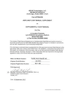
Lynx NGT-9000
Brand: L3 Aviation Products Pages: 27
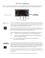
STX 165
Brand: Dallas Pages: 8

Indu Variometer
Brand: Kanardia Pages: 18
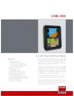
CHDD–268
Brand: Barco Pages: 2


