


Page 4-12
G1000 / GFC 700 System Maintenance Manual - 300/B300 Series King Air
Revision 1
190-00716-01
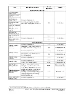
Item Description/Procedure Initials
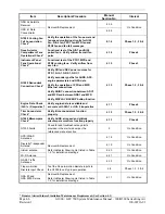
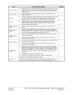
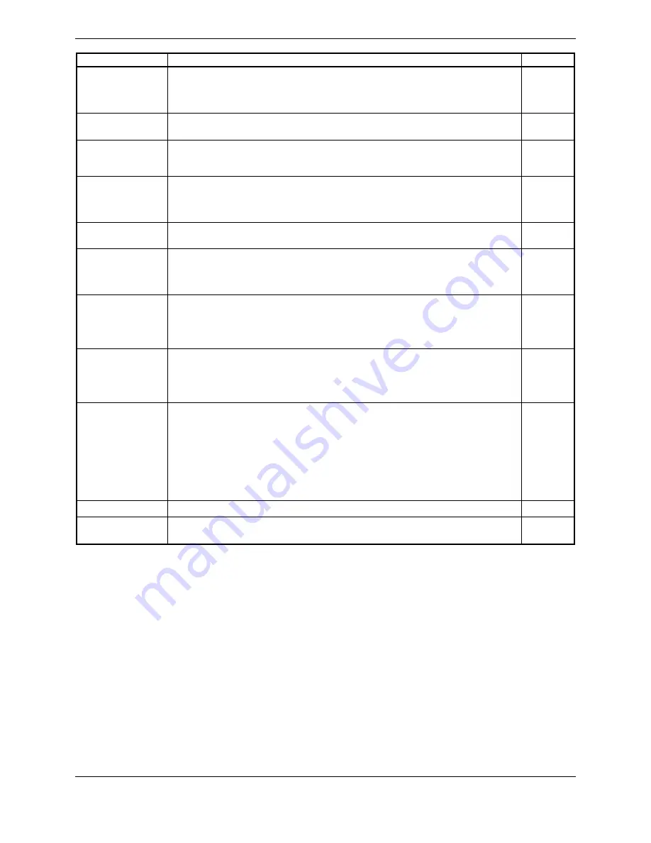
GMA 1347D (Qty 2)
a)
Inspect the GMA 1347D unit (including face of unit), rack and connectors for corrosion
or other defects. Check the integrity of the SHIELD BLOCK ground attachments to
the harness connector assembly as well as the integrity of the individual shields and
their attachment.
GDU Fans (Qty 3)
a)
Inspect PFD and MFD fans for accumulation of dirt and other damage. Remove
excess dirt as required.
GDL 69A
a)
Inspect the GDL 69A unit, rack, and connectors for corrosion or other defects. Check
the integrity of the SHIELD BLOCK ground attachments to the harness connector
assembly as well as the integrity of the individual shields and their attachment.
GMC 710
a)
Inspect the GMC 710 unit (including face of the unit), mount, and connectors for
corrosion or other defects. Check the integrity of the SHIELD BLOCK ground
attachments to the harness connector assembly as well as the integrity of the
individual shields and their attachment.
Signal Conditioners
(Qty 2)
a)
Inspect the signal conditioner unit, mount, and connectors for corrosion or other
defects.
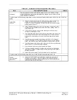
Standby Attitude
Indicator
a)
Inspect the standby attitude indicator unit (including face of unit) and connector for
corrosion or other defects. Check the integrity of the harness connector assembly in
accordance with AC 43.13-1B, Chapter 11, Section 8, Paragraphs 11-96 and 11-100
and the Cabin Wire Harness Routing drawing, listed in Table 1-2.
Standby Airspeed
Indicator
a)
Inspect the standby airspeed indicator unit (including face of unit) and connector for
corrosion or other defects
.
b)
Visually inspect the plumbing and harness connector assembly, and ensure it is
secure and in good condition.
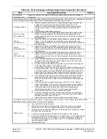
Standby Altimeter
a)
Inspect the standby altimeter indicator unit (including face of the unit) and connector
for corrosion or other defects
.
b)
Visually inspect the plumbing and harness connector assembly, and ensure it is
secure and in good condition.
Circuit Breaker
Panels
a)
Inspect circuit breaker panel wiring and circuit breakers for chafing, damage, other
defects and proper routing of wire bundles and security of attachment in accordance
with AC 43.13-1B, Chapter 11, Section 8, Paragraph 11-96, the appropriate Circuit
Breaker Panel Modification drawing, listed in Table 1-2, and the Cabin Wire Harness
Routing drawing, listed in Table 1-2. Pay particular attention to possible areas of
chaffing.
b)
Inspect edgelit overlay panels for damage or defect.
c)
Reinstall the circuit breaker edgelit overlays to the circuit breaker panels.
Reinstall the MFD and PFDs as described in Section 6.
Placards
Inspect that all required placards are installed. Placards must be legible, secure and in
good condition. Refer to the Main Instrument Panel Installation drawing listed in Table 1-2.
Summary of Contents for Cessna Caravan G1000
Page 2: ...This page intentionally left blank...
Page 89: ......