


G1000 / GFC 700 System Maintenance Manual - 300/B300 Series King Air
Page 4-15
190-00716-01
Revision 1
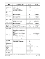
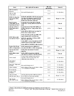
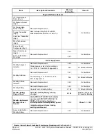
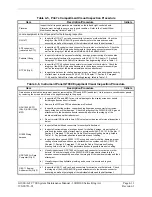
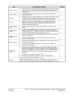
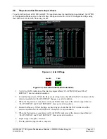
Table 4-9, Lightning Strike Inspection Procedure
Item Description/Procedure Initials
GTP 59 OAT Probe
or Antenna
a)
A post lightning strike inspection must be done for a suspected or actual lightning strike to
antennas or the OAT probes. Inspect antenna/probe and surrounding installation to ensure
that there is no structural damage around the areas where lightning may have attached. If
there is visible sign of damage to the probe or antenna, then it should be replaced per section
6. Refer to the Hawker Beechcraft Structural Inspection and Repair Manual listed in Table 1-2
for any aircraft structural repairs.
4.5 Electrical
Bonding
Test
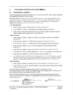
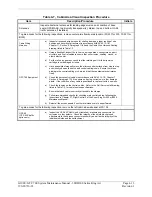
The following bonding tests are provided for G1000-equipped 300/B300 King Air aircraft as a
requirement beyond what is given in the aircraft maintenance manual. The electrical bonding checks are
split into two tests, Phase 3 Electrical Bonding Test and Phase 4 Electrical bonding test. This places the
bonding test requirement for each G1000 LRU in the same phase as the visual inspection of that zone to
minimize access requirements.
4.5.1
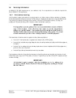
Requirements
All G1000 equipment must be installed. Gain access for the procedures in Sections 4.5.3 and 4.5.4 as
required and in accordance with the Super King Air 300 or B300 Maintenance Manual. It is
recommended that these tests are conducted after visual inspection of the zone to minimize access
requirements.
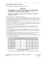
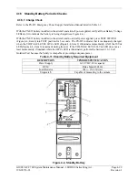
4.5.2
Test Equipment
A milli-ohm meter and Kelvin probes are recommended for this test. However, a standard voltmeter,
power supply with adjustable current limit, and ammeter may be substituted. The following procedure is
written using the voltmeter, power supply and ammeter. All test equipment must have valid calibration
records.
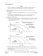
4.5.3
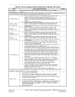
Phase 3 Electrical Bonding Procedure
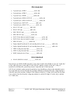
1.
Connect the positive lead of the power supply to the engine compartment grounding bracket (battery
negative connection to the airframe). Connect/touch the positive lead of the voltmeter to the same
point.
NOTE
Ensure that the voltmeter and power supply probes do not touch, so as not to induce
contact resistance.
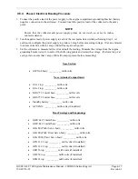
2.
Touch negative lead of power supply to each of the test points listed while performing Step 3. At
each point, configure the power supply to produce 1 amp before measuring voltage. (Use an
ammeter to ensure current is within 1 amp ±100 milli-amp at each point).
3.
Set the voltmeter to measure milli-volts and null the reading. Measure the voltage from the engine
grounding bracket (step 1) to each of the following points and record the voltage. (Perform Step 2 at
each point to ensure that 1 amp ±100 milli-amp is present before measuring.)
Summary of Contents for Cessna Caravan G1000
Page 2: ...This page intentionally left blank...
Page 89: ......


