G1000 / GFC 700 System Maintenance Manual - 300/B300 Series King Air
Page 4-17
190-00716-01
Revision 1
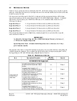
4.5.4
Phase 4 Electrical Bonding Procedure
1.
Connect the positive lead of the power supply to the engine compartment grounding bracket (battery
negative connection to the airframe). Connect/touch the positive lead of the voltmeter to the same
point.
NOTE
Ensure that the voltmeter and power supply probes do not touch, so as not to induce
contact resistance.
2.
Touch negative lead of power supply to each of the test points listed while performing Step 3. At
each point, configure the power supply to produce 1 amp before measuring voltage. (Use an ammeter
to ensure current is within 1 amp ±100 milli-amp at each point).
3.
Set the voltmeter to measure milli-volts and null the reading. Measure the voltage from the engine
grounding bracket (step 1) to each of the following points and record the voltage. (Perform Step 2 at
each point to ensure that 1 amp ±100 milli-amp is present before measuring)
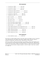
Nose Section
•
GWX 68 body: __________ milli-volts
Nose Avionics Compartment
•
GIA 1 top: __________ milli-volts
•
GIA 2 top: __________ milli-volts
•
GRS 77 #1 metal base: __________ milli-volts
•
GRS 77 #2 metal base: __________ milli-volts
•
Standby battery: __________ milli-volts
•
GTS 8XX: __________ milli-volts (if installed)
Rear Fuselage and Empennage
•
GMU 44 #1 metal base: __________ milli-volts
•
GMU 44 #2 metal base: __________ milli-volts
•
GSA 80 (Pitch) Servo body: __________ milli-volts
•
GSA 80 (Pitch Trim) Servo body: __________ milli-volts
•
GSA 9000 (Yaw) Servo body: __________ milli-volts
•
GTX 33 #1 top: __________ milli-volts (if installed)
•
GTX 33 #2 top: __________ milli-volts (if installed)
•
GSR 56 top: __________ milli-volts (if installed)
•
GDL 59 top: __________ milli-volts (if installed)
•
GSD 41 top: __________ milli-volts (if installed)
Summary of Contents for Cessna Caravan G1000
Page 2: ...This page intentionally left blank...
Page 89: ......


