G1000 / GFC 700 System Maintenance Manual - 300/B300 Series King Air
Page 4-29
190-00716-01
Revision 1
4.16 Standby Battery Periodic Checks
4.16.1
Charge Check
Refer to the PS-835 Emergency Power Supply Installation Manual listed in Table 1-2.
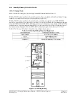
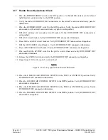
With the PS-835 battery installed in the aircraft and aircraft power applied, verify all four Battery Voltage
LEDs are lit to indicate the battery is being charged (see Figure 4-4
).
With the PS-835 battery installed in the aircraft and no aircraft power applied, press TEST SWITCH
(Figure 4-4, Item 4) into TEST position for 5 seconds. The PS-835 indicates that it is adequately charged
when the VOLTAGE LEVEL 24Vdc LED (Figure 4-4, Item 2) illuminates momentarily, AND the 20Vdc
LED (Figure 4-4, Item 6) remains lit during the test. If the VOLTAGE LEVEL 24Vdc LED does not, at
least momentarily, illuminate while the 20Vdc LED is illuminated, perform the Section 4.16.3 Cell
Isolation Test because the battery is incapable of providing adequate power.
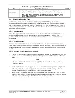
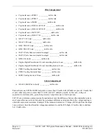
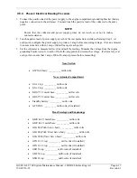
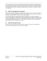
Table 4-11, Standby Battery Required Equipment
DESCRIPTION VENDOR/SPECIFICATION
Power Supply
0-30 VDC, 20A capacity
DVM Fluke
Model
8050A
Load Resistor
7
Ω
+/- 1% 250 watt
Stopwatch
Capable of measuring to the minute
Figure 4-4, Standby Battery
Summary of Contents for Cessna Caravan G1000
Page 2: ...This page intentionally left blank...
Page 89: ......

