


G1000 / GFC 700 System Maintenance Manual - 300/B300 Series King Air
Page 6-5
190-00716-01
Revision 1
6.8
GRS 77 AHRS
Removal:
1.
Gain access to the forward avionics compartment in the nose of the aircraft.
2.
Disconnect the AHRS connector.
3.
Loosen the four Phillips thumbscrews with a screwdriver until they are free from the rack.
4.
Gently lift the GRS 77 from the mounting rack. (If the mounting rack is removed, the GRS 77
must be re-calibrated. Do not loosen mounting bolts. See Section 7.7)
Reinstallation:
1.
Visually inspect the connectors to ensure there are no bent or damaged pins. Repair any damage.
2.
Place the GRS 77 on the mounting plate, ensuring the orientation is correct.
3.
Fasten the unit to the plate using the Phillips thumbscrews.
4.
Connect the connector to the GRS 77.
5.
Calibrate and test the GRS 77 according to Section 7.7.
6.9
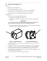
GMU 44 Magnetometer
Removal:
1.
Disconnect electrical wiring harnesses and remove the tailcone.
2.
Loosen three screws connecting the unit to the aircraft mounting bracket using a non-magnetic
Phillips screwdriver.
3.
Remove the cable tie attaching the magnetometer pigtail harness to the shelf.
Reinstallation:
1.
Visually inspect the connectors to ensure there are no bent or damaged pins. Repair any damage.
2.
Fasten the GMU to the aircraft mounting bracket using a non-magnetic Phillips screwdriver.
3.
Attach the magnetometer pigtail harness to the shelf with a cable tie
4.
Reinstall tailcone and connect the electrical wiring harnesses.
5.
Calibrate and test the GMU 44 according to Section 7.7.
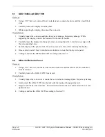
6.10 GDL
69A
Removal:
1.
Gain access by removing the right side GDU 1040A display unit (see Section 6.1.)
2.
Unlock the GDL 69A handle by loosening the Phillips screw on the handle.
3.
Pull the handle upward to unlock the GDL 69A. Gently remove the unit from the rack.
Reinstallation:
1.
Visually inspect the connectors to ensure there are no bent or damaged pins. Repair any damage.
2.
Gently insert the GDL 69A into its rack. The handle should engage the dogleg track.
3.
Press down on the GDL 69A handle to lock the unit into the rack.
4.
Lock the handle to the GDL 69A body using the Philips screw.
5.
Configure and test the GDL 69A according to Section 7.8.
Summary of Contents for Cessna Caravan G1000
Page 2: ...This page intentionally left blank...
Page 89: ......