


G1000 / GFC 700 System Maintenance Manual - 300/B300 Series King Air
Page 2-5
190-00716-01
Revision 1
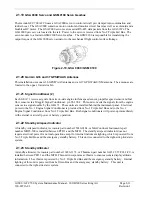
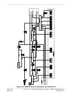
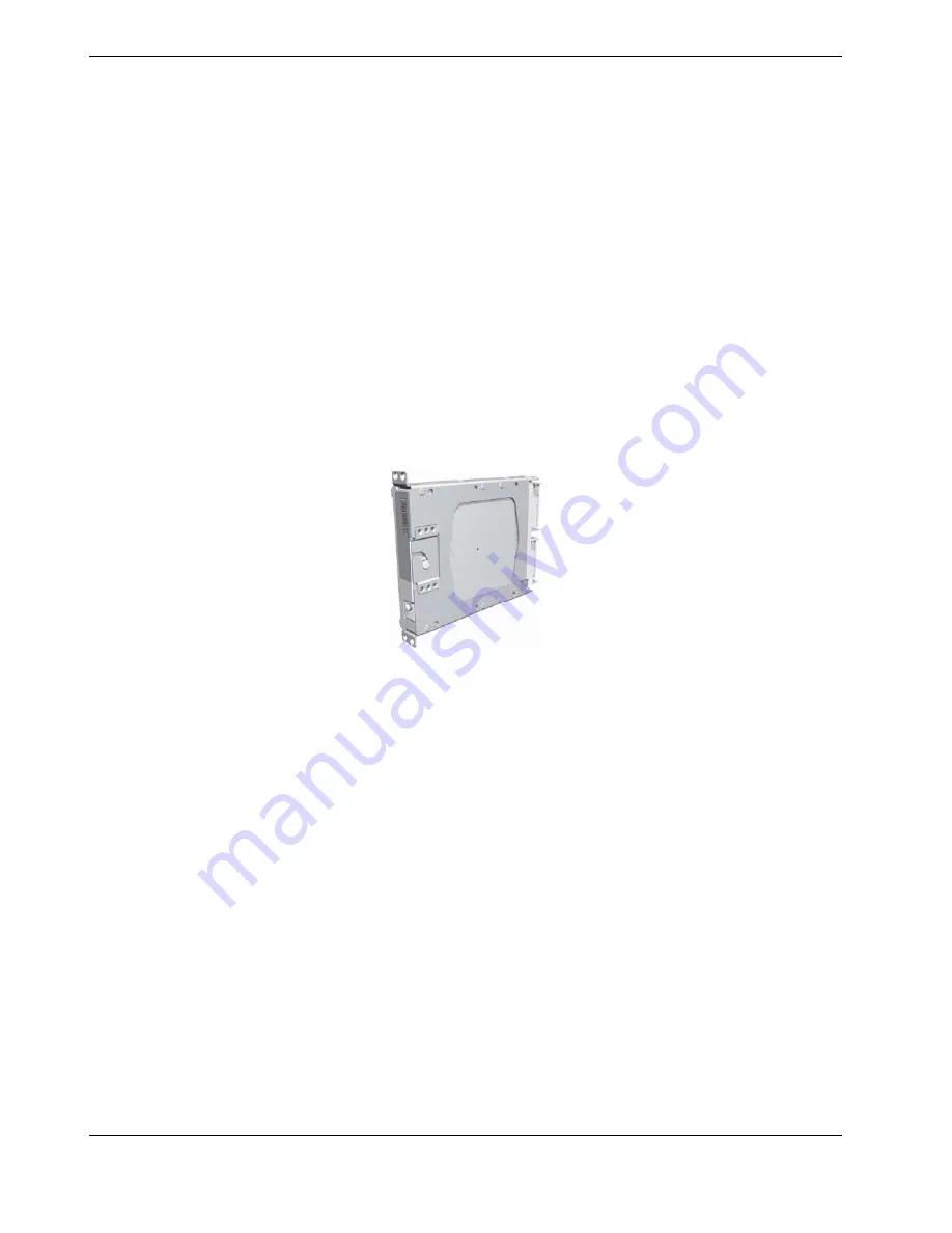
2.1.7
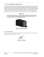
GEA 71 Engine/Airframe Unit (2)
The Garmin GEA 71 Engine/Airframe Units provide engine/airframe data to the G1000 system. Data
received from transducers/sensors is processed and sent to GIA 63Ws (via RS-485 digital interface), and
subsequently to the GDU 1500 MFD. Engine parameters are normally displayed on the MFD. In the event
of MFD failure, the engine parameters can be displayed on PFD 1 and/or PFD 2 using display reversion.
The GEAs are located behind the instrument panel and is mounted in a vertical orientation. Electrical power
to GEA 1 is provided from No. 1 Triple Fed Bus and to GEA 2 from No. 2 Triple Fed Bus. Both GEA units
will power-up immediately with external or aircraft power or battery operation.
Each GEA interfaces to the following sensors for its onside engine:
•
Oil Pressure Sensor
•
Oil Temperature Sensor
•
Fuel Flow Sensor (via onside Signal Conditioner)
•
Turbine Speed Sensor (via onside Signal Conditioner)
•
Propeller Speed Sensor(via onside Signal Conditioner)
•
Torque Sensor
•
Interstage Turbine Temperature (ITT) Sensor
Figure 2-7, GEA unit
Summary of Contents for Cessna Caravan G1000
Page 2: ...This page intentionally left blank...
Page 89: ......