


Page 7-10
G1000 / GFC 700 System Maintenance Manual - 300/B300 Series King Air
Revision 1
190-00716-01
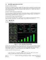
7.4.2
GEA Engine Indication Checks
Perform engine indicating systems checks for the following left and right engine indications:
Reference Hawker Beechcraft King Air 300/300LW or B300/B300C Maintenance Manual, Chapter
77-00-00, “Engine Indicating – Maintenance Practices”.
•
ITT
•
N1
•
N2
•
Torque
7.4.3
GEA Fuel Flow Indication Functional Check
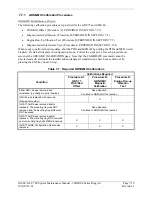
The special tools and equipment listed in Table 7-1 are provided for reference only and are not
specifically required. Any product conforming to the specification listed may be used. It is the
responsibility of the technician or mechanic to determine the applicable specification prior to testing.
Table 7-1, Fuel Flow Indication Special Equipment
Name Requirement
Decade Box
0-1k ohms
Signal Generator
0-10Vdc / 0 – 1k Hz
The following steps are required to be completed on both engines as necessary.
1.
Remove the engine cowling (Ref. Hawker Beechcraft King Air 300/300LW or B300/B300C
Maintenance Manual, Chapter 71-10-00) to gain access to the engine MT5 fuel flow transmitter
connector (P6).
2.
Disconnect the P6 connector from the fuel flow transmitter.
3.
Connect the Decade Box, set to a resistance of 1000
Ω
, to pins C and D of the P6 connector.
4.
Connect the Signal Generator to pins A (+) and B (-) of the P6 connector.
5.
Apply external power to aircraft.
6.
Set the BAT, EXT PWR and AVIONICS MASTER PWR switches to ON.
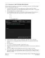
7.
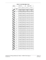
Inject a 25 mV P-P signal with the signal generator and simulate the frequencies specified in the
table below.
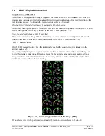
8.
Observe MFD in normal mode and verify fuel flow indications match those values listed in Table
7-2.
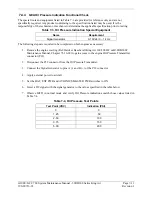
Table 7-2, Fuel Flow Test Points
Test Point (Hz)
Indication (PPH)
0 0
140 100
561 400
841 600
1122 800
Summary of Contents for Cessna Caravan G1000
Page 2: ...This page intentionally left blank...
Page 89: ......