Page 4-6
G1000 / GFC 700 System Maintenance Manual - 300/B300 Series King Air
Revision 1
190-00716-01
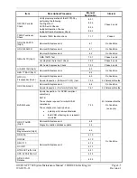
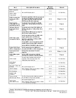
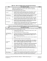
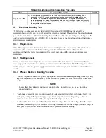
Item Description/Procedure
Manual
Section No.
Interval
GSR 56 Satellite
Receiver
Removal & Replacement
6.35
On Condition
GSD 41 Data
Concentrator
6.36
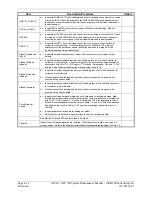
G1000 Cooling Fan
Fail Annunciation
Check*
Verify the operation of the fan power and
fan speed monitoring circuits for GIA1
Fan, GIA2 fan, PFD1 fan, MFD fan and
PFD2 fan and fan fail messages
8.1.4
Phase 1, 2, 3 & 4
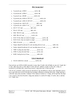
Nose Avionics
Compartment Fans
Operational Check*
Functional test of the GIA1 and GIA2
ported fans. Verify airflow from all fan
ports
4.14 Phase
4
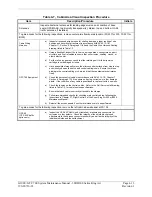
Instrument Panel
Fans Operational
Check*
Functional test of the PFD1, MFD and
PFD2 cooling fans. Verify airflow from
each fan
4.15 Phase
3
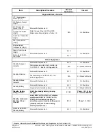
G1000 Redundant
Connection Check*
Verify PRI and SEC power sources for
PFD 1, GIA 1, GRS 1, GDC 1
Verify secondary paths for AHRS, ADC,
engine parameters and GPS data
Verify the operation of PFD and MFD
Ethernet connections
Verify ARINC connection between ADC1
and MFD and between GRS1 and MFD
Verify DISPLAY BACKUP button function
4.10
Phase 1, 2, 3 & 4
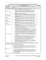
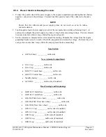
Engine Data Check
(GIA 1 or 2 Inoperative)*
Verify engine data is available and
accurate with GIA 1 or GIA 2 inoperative
4.11 Phase
4
Trim Annunciator
Check*
Verify trim annunciators function
properly
4.12
Phase 1, 2, 3 & 4
G1000 Miscompare
Check*
Verify AHRS, airspeed and altitude
miscompare monitors function properly
4.13 Phase
4
G1000 Alerts
Check for and troubleshoot any alerts
provided in the alert window per the
referenced manual section
5 On
Condition
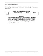
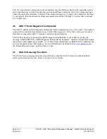
GPS/WAAS
Antennas
Removal & Replacement
Refer to Master Drawing List, listed in Table
1-2, for installation drawings.
6.18 On
Condition
Diversity Transponder
Antenna
6.19 On
Condition
Iridium antenna
6.20
On Condition
Wi-Fi Antenna
6.21
On Condition
GA 58 Traffic
Antennas
6.33 On
Condition
Flaps-in-motion
Discrete Input Check
Test the Flaps-in-motion discrete inputs to
the G1000 to verify proper operation.
4.8
Phase 1, 2, 3 & 4
GSA 80 and
GSA 9000 Servos
Removal & Replacement.
Refer to Master Drawing List, listed in Table
1-2, for installation drawings.
6.11 On
Condition
*
Denotes Airworthiness Limitation Maintenance Requirement (See Section 4.1)
Summary of Contents for Cessna Caravan G1000
Page 2: ...This page intentionally left blank...
Page 89: ......

