____________________________________________________________________
G1000 System Maintenance Manual
Page 5-85
190-00903-00
Rev.
A
5.1.8.6 GEA Status Page
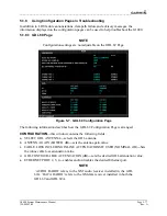
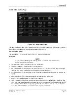
Figure 5-11. GEA Status Page
This page displays various items related to the GEA 71 and its operation. The technician can use
this page to aid in diagnosis and troubleshooting of the GEA 71.
SELECT GEA UNIT:
This box displays the currently selected GEA 71 engine/airframe unit.
STATUS:
NOTE
A green box indicates good working order. A red box indicates an issue.
Contact Garmin for assistance.
a.
CALIBRATE
―
Displays status of GEA 71 calibration.
b.
CONFIG
―
Displays status of GEA 71 configuration.
c.
INT PWR SUPPLY
―
Displays status of the GEA 71 +5, +10, and +12 sensor power supply
voltages. If it is red, troubleshoot as for Engine Instrument Red-X’s.
d.
EEPROM MAIN, A, B
―
Displays status of internal EEPROM for main, I/O ‘A’ and I/O ‘B’
boards.
e.
RAM, ROM, XILINX
―
Displays status of internal memory and FPGA.
f.
RS-485 1, 2
―
Displays status of RS-485 I/O channels.
g.
COM CHANNEL
―
Displays whether or not the main RS-485 channel usage is greater than
80%. Red indicates a utilization of greater than 80%, whereas green indicates a utilization of
less than 80% of the channels’ capacity (preferred). A red box is not cause for replacement
of the unit, it is an indicator of communication capacity utilization.


