______________________________________________________________________________
____________________________________________________________________________
Page 7-14
LMM for the Kodiak 100
190-02102-00 Rev.4
Any degaussing of the area near the GMU 44(B) mounting location requires repeating
the magnetometer calibration procedure (Procedure B), and if recommended initially, the
heading offset compensation procedure (Procedure C).
A repeat of the pitch/roll offset procedure (either Procedure A-1 or A-2) requires a repeat
of the magnetometer calibration procedure (Procedure B), and also (if previously
recommended) a repeat of the heading offset compensation procedure (Procedure C).
The addition, removal or modification of components that are ferrous, or otherwise
magnetic, within 10.0 feet of the GMU 44IB) Magnetometer location after the
magnetometer interference test or magnetometer calibration procedure were completed
requires a repeat of both procedures.
Furthermore, electrical changes to the installation that affect components within 10.0 feet
of the GMU 44(B) magnetometer after the magnetometer calibration and magnetometer
interference procedures were completed will require a repeat of the magnetometer
interference test. If new magnetic interference is detected, it must be resolved and the
magnetometer calibration procedure must be repeated. Wiring or grounding changes
associated with a device located in the same wing as the GMU 44(B) is a good example
of such a change.
7.6.1 Calibration Procedure A-1: Pitch
NOTE
Either procedure A-1 or procedure A-2 is required for all installations. Pro-
cedure A-1 is preferred.
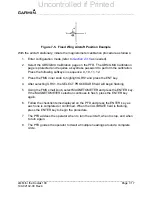
1. Level the aircraft to within ±0.25° of zero pitch and zero roll.
2. Enter configuration mode (refer to
as needed).
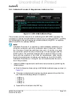
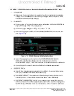
3. Select the GRS/GMU Calibration page on the PFD. The GRS/GMU Calibration
page is protected and requires a keystroke password to perform the calibration.
Press the following softkeys in sequence: 9, 10, 11, 12.
4. Press the FMS small knob to highlight GRS1. Press the ENTER key. The
SELECT PROCEDURE field is flashing. The FMS small knob can now be used to
select which calibration/validation procedure to run.
5. Select PITCH/ROLL OFFSET, then press the ENTER key. If the PITCH/ROLL
OFFSET selection is still flashing, press the ENTER key again.
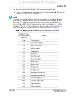
6. Follow the checklist items displayed on the PFD and press the ENTER key as
each one is completed or confirmed. When the CALIBRATE field is flashing,
press the ENTER key to begin the procedure.
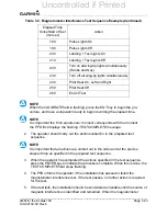
7. After several seconds, a new checklist appears in the lower half of the PFD.
Press the ENTER key as each item is confirmed. When the CONFIRM AIR-
CRAFT IS LEVEL field is flashing, press the ENTER key to continue.
Uncontrolled if Printed
Summary of Contents for Cessna Caravan G1000
Page 2: ...BLANK PAGE Uncontrolled if Printed...
Page 288: ...Uncontrolled if Printed...

