______________________________________________________________________________
____________________________________________________________________________
Page 4-10
LMM for the Kodiak 100
190-02102-00 Rev.4
4.3.19 AIL (Number 19)
1. Check the GEA 71/GEA 71B wiring.
2. Replace the GEA 71/GEA 71B.
4.3.20 Assorted Engine/Airframe Sensors (Number 20)
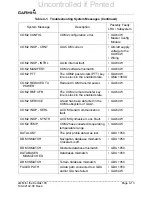
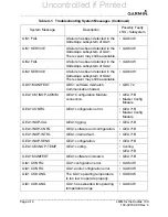
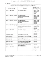
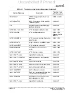
1. 1.Check the PFD Alert Window for GIA1/2 or GEA configuration, software or
failed data path error messages. Correct any errors before proceeding.
2. On PFD1 in Configuration Mode, Select the GEA STATUS page and verify the
GEA internal power supply, configuration, and calibration status boxes are
checked green.
3. If the internal power supply box displays a red X, check for shorted engine/
airframe sensors that receive 5V, 10V or 12V power from the GEA are:
• 12V-TKS Flow Sensor, TKS QTY Sensor, Fuel Sensors, Fuel Flow Sensor,
Aileron Trim Servo.
• 10V- Pitot and Stall Heat Current Sensors.
• Fuel OFF Indication.
4. The configuration and calibration boxes should be checked green. If the
calibration status boxes are red X, replace the GEA 71/GEA 71B.
5. Verify the internal, external, and reference voltages listed in the Main Analog and
I/O A Analog boxes do not display dashes (does not include Aircraft Power 1 and
2). If any voltages display dashes, replace the GEA 71/GEA 71B.
6. Check the MFD AUX - SYSTEM STATUS page if the GEA is online (green check
on the AUX - SYSTEM STATUS page is present). If GEA is not online (red X is
present), verify the unit is receiving power at the GEA rack connector.
7. If the problem persists, check the GIA/GEA interconnect wiring and unit
connector pins for faults. Replace the GEA configuration module and
thermocouple located in the back shell of the GEA connector.
8. If the problem persists, replace the GEA 71/GEA 71B.
Uncontrolled if Printed
Summary of Contents for Cessna Caravan G1000
Page 2: ...BLANK PAGE Uncontrolled if Printed...
Page 288: ...Uncontrolled if Printed...

