


__________________________________________________________________________
P
age 6-2
Garmin Perspective™ Line Maintenance Manual
Rev. E
190-00920-00
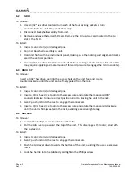
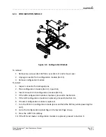
6.2
GDUs
To
remove:
1.
Use
a
3/32”
hex
drive
tool
and
turn
each
of
the
four
locking
sockets
¼
turn
counterclockwise
until
they
reach
their
stops.
2.
Disconnect
Backshell
assembly
from
unit.
3.
Remove
and
save
the
terrain
SD
Card.
Remove
the
Cirrus
data
card
located
in
the
top
slot
of
the
MFD.
To
install:
1.
Inspect
connector(s)
for
damaged
pins.
2.
Connect
Backshell
assembly
to
unit.
3.
Hold
unit
flush
with
the
instrument
panel,
making
sure
the
locking
stud
alignment
marks
are
in
the
vertical
position.
4.
Use
a
3/32”
hex
drive
tool
to
turn
each
of
the
four
locking
sockets
¼
turn
clockwise
(this
may
require
applying
a
small
amount
of
forward
pressure
to
engage
the
¼
turn
sockets).
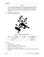
6.3
GMA
347
To
remove:
Insert
a
3/32”
hex
drive
tool
into
the
access
hole
on
the
unit
face
and
rotate
counterclockwise
until
the
unit
can
be
freely
pulled
from
the
rack.
To
install:
1.
Inspect
connector(s)
for
damaged
pins.
2.
Insert
a
3/32”
hex
drive
tool
into
the
access
hole
and
rotate
the
mechanism
90°
counterclockwise
to
insure
correct
position
prior
to
placing
the
unit
in
the
rack.
3.
Gently
push
unit
into
the
rack
to
engage
the
connectors.
4.
Insert
a
3/32”
hex
drive
tool
into
the
access
hole
and
rotate
the
mechanism
clockwise
until
the
unit
is
firmly
seated
in
the
rack,
avoiding
excessive
tightening.
6.4
GIA
63W
To
remove:
1.
Loosen
the
Phillips
screw
to
unlock
unit
handle.
2.
Pull
the
GIA
lever
up
towards
the
top
of
the
unit.
This
disengages
the
locking
stud
with
the
dogleg
slot.
To
install:
1.
Inspect
connector(s)
for
damaged
pins.
2.
Gently
push
unit
into
the
rack
to
engage
the
connectors.
3.
Push
the
GIA
lever
down
towards
the
bottom
of
the
unit,
avoiding
the
use
of
excessive
force.
4.
Lock
the
handle
into
the
GIA
body
and
tighten
the
Phillips
screw.
Summary of Contents for Cirrus Perspective SR20
Page 2: ......


