


echo™ Installation Instructions
Important Safety Information
WARNING
See the
Important Safety and Product Information
guide in the
product box for product warnings and other important
information.
CAUTION
Always wear safety goggles, ear protection, and a dust mask
when drilling, cutting, or sanding.
NOTICE
When drilling or cutting, always check what is on the opposite
side of the surface.
Registering Your Device
Help us better support you by completing our online registration
today.
• Go to
http://my.garmin.com
.
• Keep the original sales receipt, or a photocopy, in a safe
place.
Contacting Garmin Product Support
• Go to
www.garmin.com/support
and click
Contact Support
for in-country support information.
• In the USA, call (913) 397.8200 or (800) 800.1020.
• In the UK, call 0808 2380000.
• In Europe, call +44 (0) 870.8501241.
Tools Needed
• Drill and drill bits
• #2 Phillips screwdriver
• Marine sealant
•
3
/
8
in. wrench or socket
• Masking tape
• Hardware for the swivel mount (not included)
◦ Self-tapping, pan-head wood screws or pan-head bolts,
either size #8 or a diameter of
5
/
32
in. (4 mm)
◦ Appropriate washers and nuts (if selecting bolts)
◦ Appropriate drill bit for drilling the pilot hole
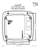
Mounting Considerations
The fishfinder device can be mounted using the included swivel-
mount bracket, or it can be mounted flush with the dashboard
using the appropriate flush-mount kit (sold separately).
Before permanently installing any part of your device, you
should plan the installation by determining the location of the
various components.
• The mounting location must provide a clear view of the
screen and access to the keys on the device.
• The mounting location must be sturdy enough to support the
device and the mount.
• The cables must be long enough to connect the components
to each other and to power.
• The cables can be routed under the swivel mount or behind
the device.
• To avoid interference with a magnetic compass, the device
should not be installed closer to a compass than the
compass-safe distance value listed in the product
specifications.
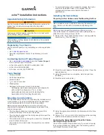
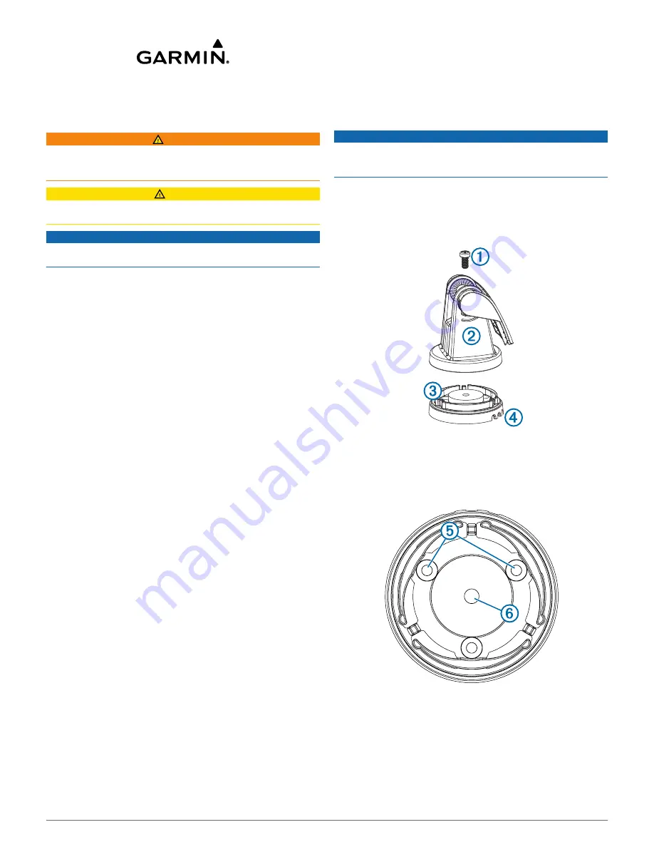
Installing the Swivel Base
Preparing to Run Cables under the Mounting Surface
NOTICE
Use pan-head screws or bolts when securing the swivel-mount
base. Screws or bolts with countersunk heads damage the
base.
Before you can prepare the swivel-mount base, you must
choose the location to install the mount and decide whether to
attach the mount using screws or bolts.
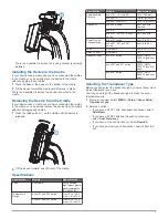
1
Remove the 10 mm M6x1 Phillips screw
À
and separate the
swivel mount
Á
from the base
Â
.
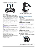
2
Orient the swivel base so the pass-through holes
Ã
face the
desired direction.
3
Using the swivel base as a template, mark the pilot hole
locations
Ä
.
4
Mark the cable routing hole
Å
.
5
Using the appropriate drill bit for the hardware, drill the three
pilot holes.
6
Using a
5
/
8
in. (16 mm) drill, drill a hole through the mounting
surface at the location you marked in step 4.
Fastening the Swivel Mount without the Cables
Running through the Mount
You should complete this procedure only if you are not running
the power and transducer cables under the mounting surface
and through the swivel-mount base.
November 2013
190-01708-02_0A
Printed in Taiwan