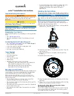
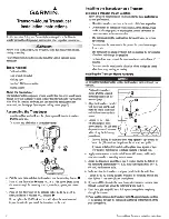
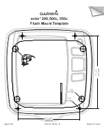
background image

1

Place the base 

À

 on the mounting surface, and fasten it 

using the appropriate screws or bolts 

Á

.

2

Place the swivel mount on the base, and replace the 10 mm 

M6×1 Phillips screw.

3

Seal the cable pass-through holes with marine sealant.

Fastening the Swivel Mount with the Cables Running 

through the Mount

You should complete this procedure only if you are running the 

power and transducer cables under the mounting surface and 

through the swivel-mount base.

1

Feed the cables through the 

5

/

8

 in. (16 mm) center hole you 

drilled when preparing to run cables beneath the mounting 

surface.

2

Place the base on the mounting surface, and fasten it using 

the appropriate screws or bolts.

3

Route the cables through the cable pass-through holes.

4

Loosely fasten the base using the appropriate screws or 

bolts.

5

Place the swivel mount on the base, but do not fasten it.

6

Place the cradle or device into the swivel mount (

Installing 

the Device in the Cradle

).

7

Pull out enough slack from the power and transducer cables 

so the mount can fully swivel to the desired positions when 

the cables are connected.

8

Remove the cradle and the swivel mount from the base.

9

Apply marine sealant to the 

5

/

8

 in. (16 mm) center hole and 

to the cable pass-through holes.

10

Securely fasten the base with the appropriate screws or 

bolts.

11

Place the swivel mount on the base, and fasten it using the 

included 10 mm M6×1 Phillips screw.

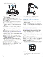
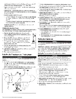
Installing the Device in the Swivel Mount

If your device uses a cradle, you must install the cradle into the 

swivel mount. If your device does not use a cradle, you must 

install the device into the swivel mount.

1

Pull up the locking arm 

À

.

2

Place the cradle or device into the swivel mount 

Á

.

3

Tilt the mount to the desired viewing angle.

4

Press down the locking arm.

Installing the Cables and Connectors

Wiring to Power

1

Route the power cable from the swivel mount to the boat 

battery or fuse block.

2

If necessary, extend the wires using 20 AWG or larger wire.

3

Connect the red wire to the positive terminal on the battery or 

fuse block, and connect the black wire to the negative 

terminal.

Connecting the Device to a Transducer

NOTE: 

The device goes into simulator mode if the connection is 

not secure between the device and transducer.
Go to 

www.garmin.com

 or contact your local Garmin

®

 dealer to 

determine the appropriate type of transducer for your needs.

1

Follow the instructions provided with your transducer to 

correctly install it on your boat.

2

Route the transducer cable to the back of your device, away 

from sources of electrical interference.

3

Connect the transducer cable to the appropriate port on your 

device.

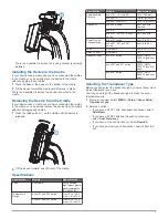
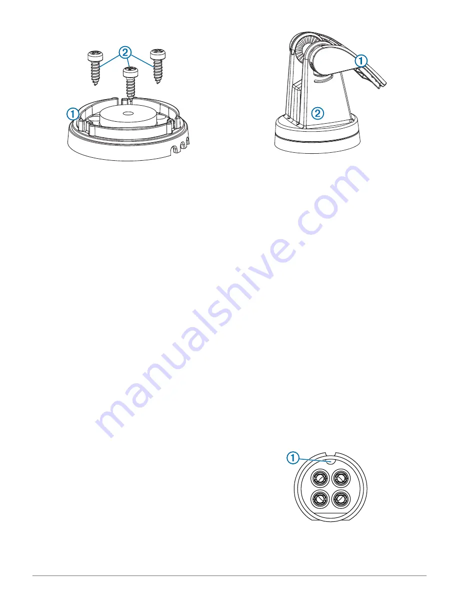
Connecting the Cables to the Device

The connectors on the cables are keyed to fit only in the correct 

ports on the device or cradle. For devices that use the mounting 

cradle, the connected cables are held in place by a locking 

bracket. For devices that do not use a mounting cradle, the 

cables connect directly to the device.

1

Compare the divots 

À

 on each cable connector to the keying 

on each port to determine which cable corresponds to each 

port.

2

Securely connect each cable to a port.

3

For devices that require the cradle, place the locking bracket 

Á

 over the cables and slide the bracket down to lock the 

cables in place.

2

Summary of Contents for echo 300 Series

Page 1: ...echo 200 300 and 500 Series Owner s Manual March 2014 190 01709 00_0B Printed in Taiwan ...

Page 2: ...al without obligation to notify any person or organization of such changes or improvements Go to www garmin com for current updates and supplemental information concerning the use of this product Garmin and the Garmin logo are trademarks of Garmin Ltd or its subsidiaries registered in the USA and other countries echo is a trademark of Garmin Ltd or its subsidiaries These trademarks may not be used...

Page 3: ...eter 3 Sonar 3 DownVü Sonar View 3 Sonar Frequencies 3 Adjusting the Range of the Depth Scale 3 Adjusting the Zoom 3 Locking the Screen to the Water Bottom 3 Pausing the Sonar Screen 3 Opening the Sonar History 3 Setting the Sonar Scroll Speed 3 Showing and Adjusting the Depth Line 4 Configuring the Appearance of Suspended Targets 4 Turning on the A Scope 4 Sonar Gain and Noise Settings 4 Alarms 4...

Page 4: ......

Page 5: ... when the power is applied Otherwise you must select Select MENU Setup System Auto Power On Adjusting the Backlight 1 Select MENU Setup System Backlight 2 Select and Adjusting the Color Scheme For the echo 300 and 500 series devices you can set the color scheme for all sonar screens 1 Select MENU Setup Sonar Setup Color Scheme 2 Select a color scheme Setting the Color Mode For the echo 300 and 500...

Page 6: ...ducer or a dual frequency transducer to use the split frequency page Select MENU Pages Split Frequency Log Page Settings Select MENU Pages Log Depth Shows a graphic log of depth readings over time Depth Log Duration Sets the time scale of the depth log Increasing the duration shows depth variations over a longer period of time Decreasing the duration shows more details over a shorter period of tim...

Page 7: ...range of the depth scale that appears on the right side of the screen Automatic ranging keeps the bottom within the lower third of the sonar screen and can be useful for tracking the bottom where there are slow or moderate terrain changes When the depth changes dramatically like a drop off or cliff manually adjusting the range allows a view of a specified depth range The bottom is shown on the scr...

Page 8: ...se automatically select Auto High To display medium sensitivity sonar returns with moderate noise automatically select Auto Med To display lower sensitivity sonar returns with less noise automatically select Auto Low Setting Noise Rejection You can decrease the appearance of weak sonar returns by increasing noise rejection NOTE Setting noise rejection on one page applies that setting to all pages ...

Page 9: ...U Setup System System Information Factory Settings 2 Select an option Calibration Setting the Keel Offset You can enter a keel offset to compensate for the surface reading for the depth of a keel making it possible to measure depth from the bottom of the keel instead of from the transducer location 1 Select an option based on the location of the transducer If the transducer is installed at the wat...

Page 10: ... screen with a soft clean lint free cloth Software License Agreement BY USING THE DEVICE YOU AGREE TO BE BOUND BY THE TERMS AND CONDITIONS OF THE FOLLOWING SOFTWARE LICENSE AGREEMENT PLEASE READ THIS AGREEMENT CAREFULLY Garmin Ltd and its subsidiaries Garmin grant you a limited license to use the software embedded in this device the Software in binary executable form in the normal operation of the...

Page 11: ...stration 1 Q quick adjust 1 R registering the device 1 S settings 1 3 system information 5 software license agreement 6 sonar 2 3 a scope 4 alarms 4 appearance 2 4 bottom lock 3 depth line 4 depth scale 2 3 DownVü 3 flasher 2 frequencies 1 4 gain 4 log 2 noise 4 numbers 2 3 5 odometer 3 scroll speed 3 suspended targets 2 4 views 2 zoom 2 3 specifications 6 system information 5 T timeout 1 transduc...

Page 12: ... 02 36 699699 52 001 855 792 7671 0800 0233937 47 815 69 555 00800 4412 454 44 2380 662 915 35 1214 447 460 386 4 27 92 500 0861 GARMIN 427 646 27 0 11 251 9999 34 93 275 44 97 46 7744 52020 886 2 2642 9199 ext 2 0808 238 0000 44 0 870 8501242 49 0 180 6 427646 20 ct Anruf a d deutschen Festnetz Mobilfunk max 60 ct Anruf 913 397 8200 1 800 800 1020 2013 2014 Garmin Ltd or its subsidiaries ...

Page 13: ...ng the location of the various components The mounting location must provide a clear view of the screen and access to the keys on the device The mounting location must be sturdy enough to support the device and the mount The cables must be long enough to connect the components to each other and to power The cables can be routed under the swivel mount or behind the device To avoid interference with...

Page 14: ...your device does not use a cradle you must install the device into the swivel mount 1 Pull up the locking arm À 2 Place the cradle or device into the swivel mount Á 3 Tilt the mount to the desired viewing angle 4 Press down the locking arm Installing the Cables and Connectors Wiring to Power 1 Route the power cable from the swivel mount to the boat battery or fuse block 2 If necessary extend the w...

Page 15: ...to 70 C echo 301 and 501 series From 5 to 131 F from 15 to 55 C Specification Models Measurement Compass Safe Distance echo 101 151 and 201 10 in 250 mm echo 301c 13 8 in 350 mm echo 501c and 551c 15 75 in 400 mm Frequency echo dv models 50 77 200 kHz DownVü echo 101 200 kHz echo 151 201 301 and 501 series 50 77 200 kHz Power Source Voltage Range echo 101 series from 10 to 20 V echo 201 301 and 50...

Page 16: ...tion No 68 Zhangshu 2nd Road Xizhi Dist New Taipei City 221 Taiwan R O C Garmin and the Garmin logo are trademarks of Garmin Ltd or its subsidiaries registered in the USA and other countries echo is a trademark of Garmin Ltd or its subsidiaries These trademarks may not be used without the express permission of Garmin 2013 Garmin Ltd or its subsidiaries www garmin com support ...

Page 17: ...Schwinger fur die Heckspiegelmontage lnstallationsanweisungen lnstrucciones de instalaci6n del transductor de montaje en el espejo de popa lnstrugoes de instalagao do transdutor com suporte para painel de papa lnstallationsvejledning til agterspejlsmonteret transducer lnstalleringsinstruksjoner for hekkmontert svinger Akterspegelmonterad givare installationsinstruktioner December 2012 Part Number ...

Page 18: ...ust be in clean non turbulent water for optimal performance Do not mount the transducer in the path ofthe propeller on single drive boats The transducer can cause cavitation that can degrade the performance ofthe boat and damage the propeller On twin drive boats mount the transducer between the drives if possible Do not mount the transducer in alocation where it might bejarred when launching hauli...

Page 19: ...the 20 in 50 em cable tie around the body ofthe trolling motor but do not fully tighten the cable tie 5 Properly align the gasket between the transducer mount and the body of the trolling motor and tighten the cable tie Ifnecessary trim the excess cable tie 6 Position the transducer so that it will be parallel with the bottom when in use tighten the 10 32locking nut e until it touches the mounting...

Page 20: ...Fax 913 397 8282 Garmin Europe Ltd Liberty House Hounsdown Business Park Southampton Hampshire S040 9LR UK Tel 44 0870 8501241 outside the UK or 0808 2380000 UK only Fax 44 0870 8501251 Garmin Corporation No 68 Zhangshu 2nd Road Xizhi Dist New Taipei City 221 Taiwan R O C Tel 886 2 2642 9199 Fax 886 2 2642 9099 Part Number 190 01315 91 Rev C ...

Page 21: ... al adresse www garmin com support si vous avez des questions au sujet de votre appareil Garmin equi per aiutarti In caso di domande sui dispositive visita il sito Web dell assistenza per prodotti Garmin all indirizzo www garmin com support prima di contattare il tuo rivenditore iGarmin esta aquf para ayudartel Antes de contactar con tu distribuidor visita Ia pagina web del servicio tecnico de Gar...

Page 22: ...tes de seguran9a edo produto 10 Belangrijke veiligheids en productinformatie 11 Vigtige produkt og sikkerhedsinformationer 13 Tarkeita turvallisuus ja tuotetietoja 14 Viktig sikkerhets og produktinformasjon 15 Viktig sakerhets och produktinformation 16 Waine informacje dotyczq_ce bezpieczeristwa i produktu 18 npas na TeXH K 6e3onaCHOCT CB9A9H 06 3Aen 19 Vazne informacije o proizvodu i sigurnosti 2...

Page 23: ...e FCC rules These limits are designed to provide reasonable protection against harmful interference in aresidential installation This equipment generates uses and can radiate radio frequency energy and may cause harmful interference to radio communications if not installed and used in accordance with the instructions However there is no guarantee that interference will not occur in aparticular ins...

Page 24: ... warranty service an original or copy of the sales receipt from the original retailer is required Garmin will not replace missing components from any package purchased through an online auction International Purchases Aseparate warranty may be provided by international distributors for devices purchased outside the United States depending on the country If applicable this warranty is provided by t...

Page 25: ...151st Street Olathe Kansas 66062 USA Garmin Europe Ltd ceg Mno2 Liberty House Hounsdown Business Park Southampton Hampshire S040 9LR UK Garmin Corporation No 68 Zangshu 2nd Road Xizhi Dist New Taipei City 221 Taiwan R O C www garm1n com October 2011 190 00720 25 Rev D Printed in Taiwan ...

Page 26: ... print dialog box Select Auto Rotate and Center to ensure the template prints in the correct orientation Important When printing the flush mount template set Page Scaling in the Adobe Acrobat print dialog box to None Page Scaling Select None Auto Rotate and Center Select with a check mark for correct orientation Properties Select the paper size Paper size example Use appropriate size paper Notice ...

Page 27: ...echo 200 500c 550c Flush Mount Template 3 8 in 9 5 mm 11 64 in 4 5 mm 4 11 32 in 110 mm 5 1 16 in 129 mm August 2011 190 01312 05 Rev B Printed in Taiwan ...

Reviews: