


Introduction
WARNING
See the
Important Safety and Product Information
guide in the
product box for product warnings and other important
information.
Registering Your Device
Help us better support you by completing our online registration
today.
• Go to
http://my.garmin.com
.
• Keep the original sales receipt, or a photocopy, in a safe
place.
Contacting Garmin Product Support
• Go to
www.garmin.com/support
and click
Contact Support
for in-country support information.
• In the USA, call (913) 397.8200 or (800) 800.1020.
• In the UK, call 0808 2380000.
• In Europe, call +44 (0) 870.8501241.
Manual Conventions
In this manual, the term “select” is used to describe these
actions.
• Highlighting a menu item and pressing
ENTER
.
• Pressing a key, such as
ENTER
or
MENU
.
When you are instructed to select menu items, small arrows
may appear in the text. They indicate that you should highlight a
series of items using and , and select
ENTER
after each
item. For example, for "select
MENU
>
Pause/Rewind Sonar
,"
select
MENU
, and then select or until
Pause/Rewind
Sonar
is highlighted, and then select
ENTER
.
Entering Numerical Values
You can enter numerical values when setting alarms or setting
an offset.
1
Select and to select the first numerical value.
2
Select or
ENTER
to advance to the next digit.
3
Repeat steps 1 and 2 to adjust all numerical values.
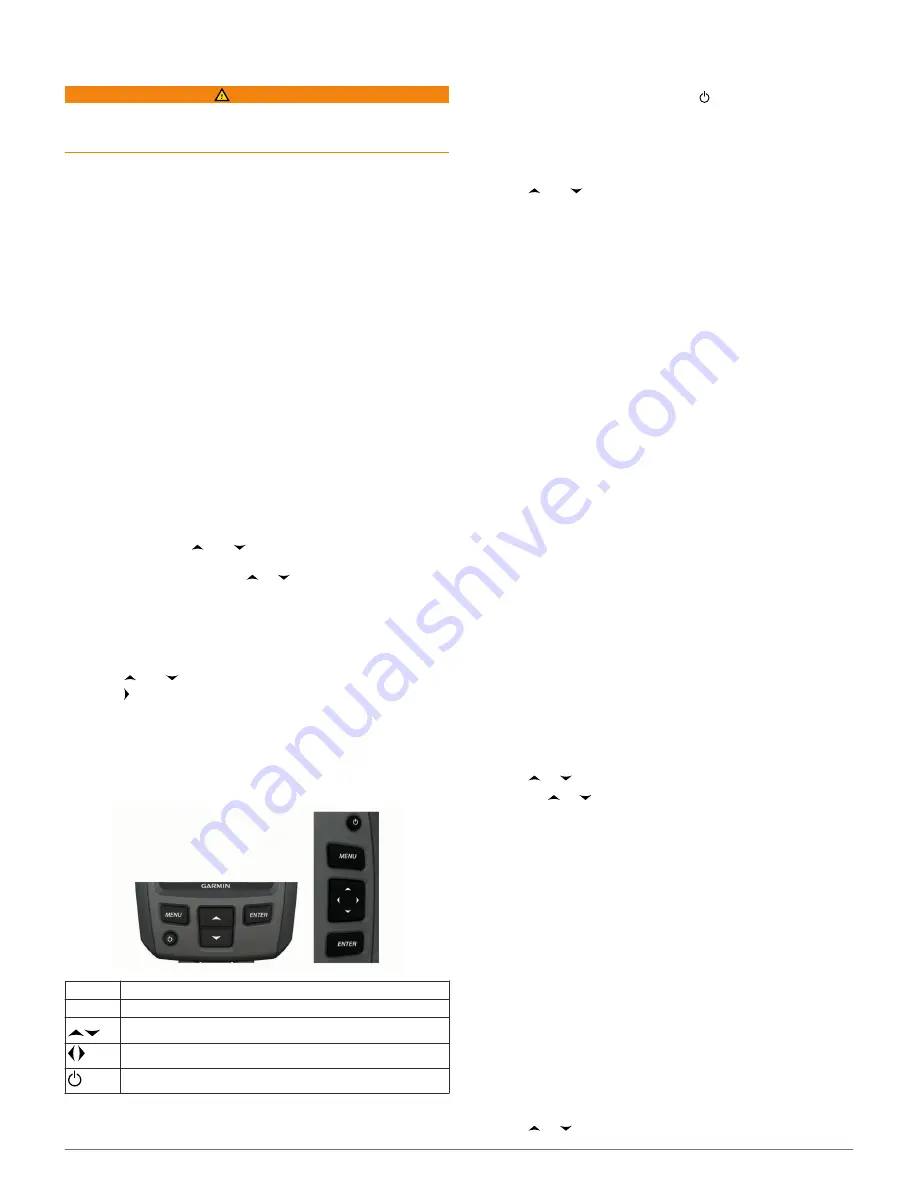
Getting Started
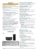
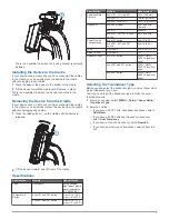
Keys
MENU
Displays or hides a list of options.
ENTER
Selects a menu item.
Scrolls through options or changes settings.
Selects page options.
Turns the device on or off and adjusts the backlight.
Turning on the Device Automatically
You can set the device to turn on automatically when the power
is applied. Otherwise, you must select .
Select
MENU
>
Setup
>
System
>
Auto Power
>
On
.
Adjusting the Backlight
1
Select
MENU
>
Setup
>
System
>
Backlight
.
2
Select and .
Adjusting the Color Scheme
For the echo 300 and 500 series devices, you can set the color
scheme for all sonar screens.
1
Select
MENU
>
Setup
>
Sonar Setup
>
Color Scheme
.
2
Select a color scheme.
Setting the Color Mode
For the echo 300 and 500 series devices, you can set the sonar
screen color mode for day or night use.
1
Select
MENU
>
Setup
>
System
>
Color Mode
.
2
Select
Day
or
Night
.
Selecting the Transducer Type
Before you can select the transducer type, you must know what
kind of transducer you have.
You may need to set the transducer type to make the sonar
function properly.
1
From a sonar view, select
MENU
>
Setup
>
Sonar Setup
>
Transducer Type
.
2
Select an option:
• If you have a 200/77 kHz, dual-beam transducer, select
Dual Beam
.
• If you have a 200/50 kHz dual-frequency transducer,
select
Dual Frequency
.
• If you have a DownVü transducer, select
DownVü
.
• If you have another type of transducer, select it from the
list.
Adjusting the Contrast
NOTE:
This feature is not available on all models.
1
Select
MENU
>
Setup
>
System
>
Contrast
.
2
Select or .
TIP:
Hold or to make large adjustments quickly.
3
Select
ENTER
.
Setting the Beeper
You can set when the device makes sounds.
1
Select
MENU
>
Setup
>
System
>
Beeper
.
2
Select an option:
• To have the device beep when you select an item and
when an alarm is triggered, select
On
.
• To have the device beep only when alarms are triggered,
select
Alarms Only
.
Menu Timeout
When a menu is open for 15 seconds and no selections are
made, the menu closes and the previous screen is displayed.
Using Quick Adjust
After adjusting a setting and returning to a page, you can
quickly return to the setting options.
Select or .
Introduction
1