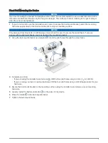
Flush Mounting the Device
NOTICE
Be careful when cutting the hole to flush mount the device. There is only a small amount of clearance between
the case and the mounting holes, and cutting the hole too large could compromise the stability of the device
after it is mounted.
Using a metal pry tool such as a screwdriver can damage the trim caps and the device. Use a plastic pry tool
when possible.
You can mount the device in your dashboard using the provided flush-mount template and hardware.
1 Trim the included template and make sure it fits in the location where you want to mount the device.
NOTE: The sun cover provided with this device has a release latch on the right side, as indicated on the
template. Be sure to allow enough clearance to access and pull the latch when selecting a location.
2 Secure the template to the mounting location.
3 Using a 12.7 mm (
1
/
2
in.) drill bit, drill one or more of the holes inside the corners of the solid line on the
template to prepare the mounting surface for cutting.
4 Using a rotary cutting tool or jigsaw, cut the mounting surface along the inside of the solid line indicated on
the template.
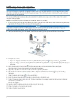
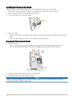
5 Secure the cradle to the back of the device (
Installing the Device in the Cradle, page 10
).
6 Place the device into the cutout to test the fit.
7 If necessary, use a file and sandpaper to refine the size of the hole.
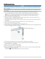
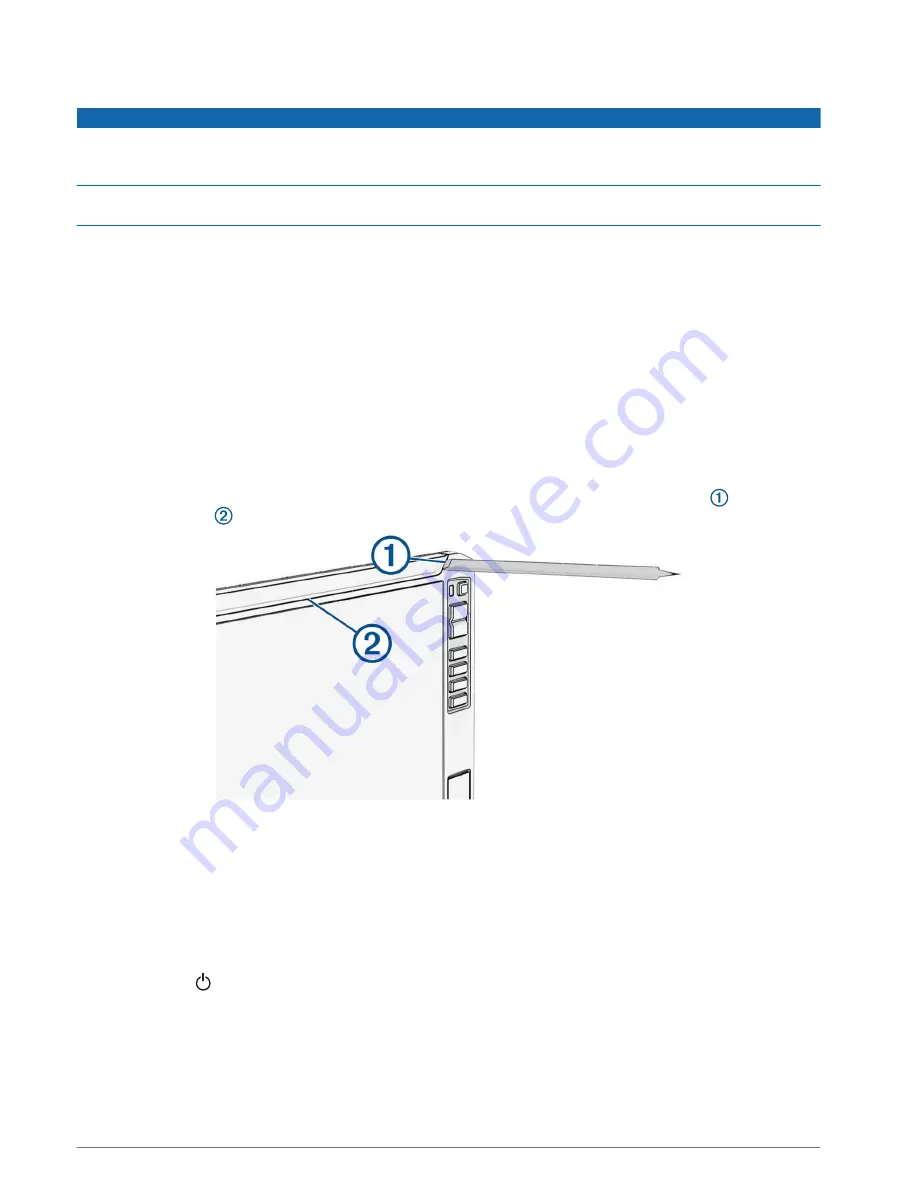
8 Use a plastic pry tool or a flat piece of plastic to carefully pry up the corners of the trim caps , slide the pry
tool to the center , and remove the trim caps.
9 Ensure the mounting holes on the device line up with the pilot holes on the template.
10 If the mounting holes on the device do not line up with the pilot holes on the template, mark the new
pilot-hole locations on your template.
11 Using a 3 mm (
1
/
8
in.) drill bit, drill the pilot holes.
12 Remove the template from the mounting surface.
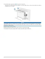
13 If you will not have access to the back of the device after you mount it, route the necessary cables through
the hole and connect them to the cradle.
You can press to power the device on and off to test the connections.
5