
1
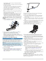
Place the cable-entry cover over the hole and the cable,
with the opening pointing downward, and mark the location of
the two pilot holes.
2
Remove the cable-entry cover, and, using a 3.2 mm (
1
/
8
in.)
bit, drill the pilot holes approximately 10 mm (
3
/
8
in.) deep.
3
Fill the pass-through hole with marine sealant so it covers the
cable completely and there is excess sealant around the hole
and the cable.
4
Place the cable-entry cover over the hole and the cable, with
the opening pointing downward.
5
Apply marine sealant to the included 12 mm M4 screws, and
attach the cable-entry cover to the transom.
6
Wipe away all excess marine sealant.
Testing the Installation
NOTICE
You should check your boat for leaks before you leave it in the
water for an extended period of time.
Because water is necessary to carry the sonar signal, the
transducer must be in the water to work properly. You cannot
get a depth or distance reading when out of the water. When
you place your boat in the water, check for leaks around any
screw holes that were added below the water line.
Testing the Transom-Mount Transducer Installation
NOTICE
When adjusting the depth of the transducer, make the
adjustments in small increments. Placing the transducer too
deep can adversely affect the performance of the boat and put
the transducer at risk of striking underwater objects.
Test the transom-mount transducer installation in open water
free of obstacles. Pay attention to your surroundings as you test
the transducer.
1
With the boat in the water, turn on the chartplotter.
2
Drive the boat at a slow speed. If the chartplotter appears to
be working properly, gradually increase speed while
observing the chartplotter.
3
If the sonar signal is suddenly lost or the bottom return is
severely degraded, note the speed at which this occurs.
4
Return the boat to the speed at which the signal was lost,
and make moderate turns in both directions while observing
the chartplotter.
5
If the signal strength improves while turning, adjust the
transducer so that it extends another
1
/
8
in. (3 mm) below the
transom of the boat.
6
Repeat steps 2–4 until the degradation is eliminated.
7
If the signal does not improve, move the transducer to a
different location on the transom, and repeat the test.
Installing the Transducer on a Trolling Motor
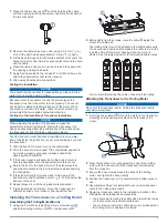
Assembling the Trolling Motor Mount
1
Using the 8 mm M4 screws and 4 mm star washers ,
attach the trolling motor mount to the transducer .
2
Before tightening the screws, route the cable inside the
mount to a cable exit.
The trolling motor mount is designed with multiple cable exits.
You should use a cable exit that allows the cable to be on the
top side of the trolling motor housing when the motor is
stowed. See the image below for recommended cable routes.
You must avoid pinching the cable or bending it too tightly.
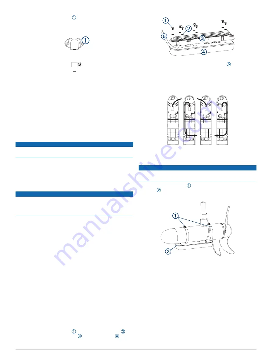
Attaching the Transducer to the Trolling Motor
NOTICE
Do not cut the transducer cable. Cutting the transducer cable
will void your warranty.
1
Insert the hose clamps through the slots on the transducer
mount , until equal lengths extend on both sides of the
mount.
2
Place the transducer mount against the body of the trolling
motor with the narrow end of the transducer pointed away
from the propeller.
3
Secure the hose clamps around the body of the trolling
motor, and tighten the hose clamps.
4
Position the transducer so it is parallel to the bottom when in
use.
5
Use waterproof tape (not included) to secure the transducer
cable to the trolling motor shaft.
6
Route the transducer cable to the installation location of the
chartplotter while taking these precautions.
• You should avoid routing the cable close to electrical wires
or other sources of electrical interference.
• You must avoid routing the cable where it is pinched when
the trolling motor is deployed or stowed.
3


