background image

190-01700-00

Flight Stream 110/210 TSO Installation Manual

Rev. B

Page 5-1

5 CONTINUED AIRWORTHINESS

5.1 Flight Stream 110

Maintenance of the Flight Stream 110 transceiver unit is on-condition.

5.2 Flight Stream 210

Maintenance of the Flight Stream 210 transceiver unit is on-condition.

Summary of Contents for Flight Stream 110/210

Page 1: ...190 01700 00 October 2014 Revision B Flight Stream 110 210 TSO Installation Manual...

Page 2: ...sed without the express permission of Garmin 2014 The Bluetooth word mark and logos are registered trademarks owned by Bluetooth SIG Inc and any use of such marks by Garmin is under license Other trad...

Page 3: ...Updated yaw pitch and roll mounting limitations 4 4 Added software update procedures Section Pagination Table of Contents iii through vi Section 1 1 1 through 1 8 Section 2 2 1 through 2 3 Section 3 3...

Page 4: ...ONS AND NOTES WARNING This product its packaging and its components contain chemicals known to the State of California to cause cancer birth defects or reproductive harm This notice is being provided...

Page 5: ...IN LIEU OF ALL OTHER WARRANTIES WHETHER EXPRESS IMPLIED OR STATUTORY INCLUDING ANY LIABILITY ARISING UNDER ANY WARRANTY OF MERCHANTABILITY OR FITNESS FOR A PARTICULAR PURPOSE STATUTORY OR OTHERWISE TH...

Page 6: ...red 2 2 2 4 Cabling and Wiring 2 2 2 5 Mounting Requirements 2 2 3 INSTALLATION PROCEDURE 3 1 3 1 Wiring Harness Installation 3 1 3 2 Flight Stream Backshell Assembly and D sub Connector 3 1 3 3 Equip...

Page 7: ...ng Locations 3 5 Figure 3 4 Flight Stream Mounting 3 6 Figure 3 5 Mounting Orientation 3 7 Figure 3 6 Mounting Orientation Side View 3 8 Figure A 1 Flight Stream Transceiver Dimensions A 1 Figure B 1...

Page 8: ...ns 1 5 Table 1 6 Flight Stream Transceiver 1 5 Table 1 7 TSO Compliance 1 6 Table 1 8 Non TSO Functions 1 6 Table 1 9 Referenced Publications 1 8 Table 2 1 Units and Part Numbers 2 1 Table 2 2 Pin Con...

Page 9: ...pose of the modification The table is current at the time of publication of this manual see date on front cover and is subject to change without notice Authorized Garmin Sales and Service Centers are...

Page 10: ...es and is not intended for use by individuals who lack the competencies set forth above For additional information see section 1 6 Limitations NOTE Except where specifically noted references made to F...

Page 11: ...and other non aviation transmitters require separate authorization for use in an aircraft If they are present note interference from such devices may degrade the performance of the Flight Stream wirel...

Page 12: ...GATOR AT A TIME IT IS RECOMMENDED TO CONNECT IT TO THE 1 NAVIGATOR OR THE GTN IN GTN GNS INSTALLATIONS Table 1 1 Flight Stream Interfaces Interface Description Number of Ports ARINC 429 In Flight Stre...

Page 13: ...ions refer to the Environmental Qualification Form 1 4 1 Environmental Qualification Form EQF It is the responsibility of the installing agency to obtain the latest revision of the Flight Stream EQF F...

Page 14: ...accordance with guidelines in AC 43 13 1B Chapter 11 Section 4 Flight Stream Transceiver Characteristics Specification Operating Temperature Range 20 C to 70 C Input Voltage Range 9 5 to 33 0 VDC Soft...

Page 15: ...compliance under 14 CFR part 43 or the applicable airworthiness requirements 1 5 1 TSO Compliance The Flight Stream is TSO C157 authorized as an incomplete system Table 1 7 TSO Compliance 1 5 2 TSO De...

Page 16: ...15 regulations Industry Canada Statement This device complies with Industry Canada license exempt RSS standard s Operation is subject to the following two conditions 1 this device may not cause interf...

Page 17: ...following publications are sources of additional information for installing the Flight Stream wireless remote system Before installing the Flight Stream the technician should read all referenced mate...

Page 18: ...e intended for use with standard aviation accessories The following items are required for installation but not supplied Wire MIL W 22759 16 or MIL W 22759 18 or equivalent If MIL W 22759 18 wire is u...

Page 19: ...appropriate wiring Once the cable assemblies have been made attach the cable connector Route the wiring bundle as appropriate Avoid sharp bends For the Flight Stream use 22 AWG wire for all connectio...

Page 20: ...into the D sub connector housing locations as specified by the interconnect drawing in appendix B 4 Verify the pin is properly engaged into the connector by gently tugging on the wire 5 Route and sec...

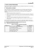
Page 21: ...ion Manual Rev B Page 3 2 3 2 2 Backshell Assembly Procedure The parts for the connector and backshell assembly for Flight Stream installations are listed in table 3 1 and shown in figure 3 1 Figure 3...

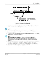
Page 22: ...t a 22 AWG wire to the exposed shield of the prepared cable assembly AC 43 13 may be a helpful reference for termination techniques NOTE Solder Sleeves with pre installed lead A preferred solder sleev...

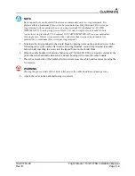
Page 23: ...it is permissible to terminate three wires per ring terminal 5 Terminate the ring terminals to the shield block by placing items on the pan head screw in the following order split washer flat washer...

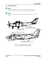
Page 24: ...plication on the connected portable electronic device PED NOTE Ensure the serial number located on the bottom of the unit is noted and saved for future reference Figure 3 3 Suggested Mounting Location...

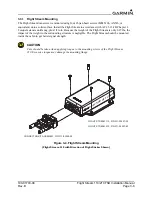
Page 25: ...Torque fasteners until snug plus 1 4 turn Because the weight of the Flight Stream is only 0 27 lbs the impact of the weight to the surrounding structure is negligible The Flight Stream should be moun...

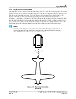
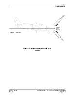
Page 26: ...h axis see figure 3 5 and figure 3 6 for details The Flight Stream may be mounted offset from the aircraft center line but must be mounted with the connector pointed in the direction of flight to with...

Page 27: ...190 01700 00 Flight Stream 110 210 TSO Installation Manual Rev B Page 3 8 Figure 3 6 Mounting Orientation Side View Pitch Axis 45 45...

Page 28: ...etion of the continuity and power checks 4 2 Bluetooth Setup 1 When the Flight Stream device is powered on the Flight Stream 110 will immediately go into pairing mode When the Flight Stream 210 device...

Page 29: ...ed gently roll the Flight Stream to the left and to the right Check that attitude matches roll on the portable electronic device c Mount Flight Stream with four 6 screws Turn the fasteners until snug...

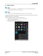
Page 30: ...e software update Garmin Pilot version 7 10 or later is required To activate Dealer Mode contact Aviation Product Support at 888 606 5482 Request access to update Flight Stream firmware as a Garmin De...

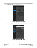
Page 31: ...Rev B Page 4 4 4 Verify Dealer Mode shows as an active subscription Figure 4 2 Garmin Pilot Settings Screen 5 Select the HOME key then the Connext key followed by the active Flight Stream device Selec...

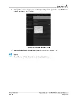
Page 32: ...vailable a popup screen will display listing current options Select Update Now or Later depending on your preference Figure 4 4 Firmware Update Popup 7 Select Continue and Begin Firmware Update on the...

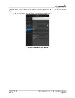
Page 33: ...llation Manual Rev B Page 4 6 The Flight Stream device will reboot once updated Allow the Flight Stream device to reconnect to Garmin Pilot 8 Verify the firmware version now displays the updated softw...

Page 34: ...tallation Manual Rev B Page 5 1 5 CONTINUED AIRWORTHINESS 5 1 Flight Stream 110 Maintenance of the Flight Stream 110 transceiver unit is on condition 5 2 Flight Stream 210 Maintenance of the Flight St...

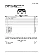
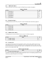
Page 35: ...Active High 6 1 1 Power The Flight Stream accepts input power from 9 5 to 33 VDC The power input pins are connected to the aircraft power bus through a single circuit breaker See appendix B for recom...

Page 36: ...ntrols of the portable electronic device When this input is Active Low i e grounded when active and open otherwise the volume up volume down and mute features are disabled All other features of the Fl...

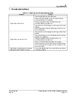
Page 37: ...that pairing mode is enabled see section 4 2 for more information Flight Stream Connection Lost Check that the control display is in RF range of the Flight Stream Check Flight Stream is not mounted b...

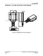
Page 38: ...ight Stream 110 210 TSO Installation Manual Rev B Page A 1 APPENDIX A OUTLINE AND INSTALLATION DRAWING Figure A 1 Flight Stream Transceiver Dimensions 2 00 3 16 2 28 0 91 1 37 0 43 2 74 0 92 3 78 5 75...

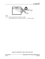
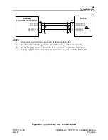
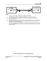
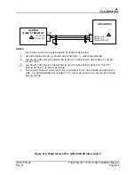
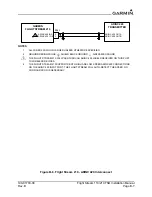
Page 39: ...INGS Figure B 1 Flight Stream 110 210 Power Interconnect Figure B 2 Flight Stream GDL 69 69A Interconnect Figure B 3 Flight Stream GDL 88 Interconnect Figure B 4 Flight Stream 210 GNS Interconnect Fig...

Page 40: ...tion Manual Rev B Page B 2 NOTES Figure B 1 Flight Stream 110 210 Power Interconnect 50 1 7 675 0 5 5 7 32 5 5281 3 5 5 7 32 5 7 1 5 5 7 5281 S 1 CIRCUIT BREAKER SHOULD BE LABELED AS SHOWN 2 GROUND DE...

Page 41: ...ESS OTHERWISE SPECIFIED 2 GROUND DESIGNATIONS SHIELD BLOCK GROUND AIRFRAME GROUND 3 ANY RS 232 PORT MAY BE CONNECTED IN LIEU OF THESE PORTS SEE SECTION 6 1 2 FOR ADDITIONAL DETAILS 4 THE FLIGHT STREAM...

Page 42: ...7 675 0 56 1 56 287 3 3 56 287 56 1 56 1 56 287 56 287 56 1 V V V V 1 ALL WIRES 22 AWG OR LARGER UNLESS OTHERWISE SPECIFIED 2 GROUND DESIGNATIONS SHIELD BLOCK GROUND AIRFRAME GROUND 3 ANY RS 422 PORT...

Page 43: ...IRFRAME GROUND 3 ANY RS 232 PORT MAY BE CONNECTED IN LIEU OF THESE PORTS FOR ADDITIONAL DETAILS SEE TABLE 6 3 4 ANY RS 232 PORT MAY BE CONNECTED IN LIEU OF THESE PORTS REFER TO THE GNS 400W AND GNS 50...

Page 44: ...CIFIED 2 GROUND DESIGNATIONS SHIELD BLOCK GROUND AIRFRAME GROUND 3 ANY RS 232 PORT MAY BE CONNECTED IN LIEU OF THESE PORTS SEE TABLE 6 3 FOR RS 232 SETTINGS 4 ANY RS 232 PORT MAY BE CONNECTED IN LIEU...

Page 45: ...LL WIRES 22 AWG OR LARGER UNLESS OTHERWISE SPECIFIED 2 GROUND DESIGNATIONS SHIELD BLOCK GROUND AIRFRAME GROUND 3 THE FLIGHT STREAM 210 WILL PASS THROUGH ARINC 429 LABELS RECEIVED ON THIS PORT TO WIREL...

Page 46: ......

Reviews: