background image

Connecting to Power

 CAUTION

The wiring (not included) from the power source to the amplifier must run through an inline fuse or circuit 
breaker (not included) as close to the power source as possible. You must connect the positive wire to the fuse 
or circuit breaker. Connecting the amplifier to power without an inline fuse or circuit breaker may result in a fire 
if there is a short in the cable.
If the amplifier is powered by a battery, use a breaker or fuse rated to protect a cable of the gauge used to 
connect the amplifier to the battery. See the American Boat & Yacht Council (ABYC) standards for the required 
fuse or breaker rating.
If the amplifier is powered by a source other than a battery, use a breaker or fuse rated no higher than the max 
current of the power source.

You should use 4 AWG (21.1 mm

2

) copper-coated aluminum wire (not included) to connect the amplifier to 

power and ground for most installations. For long power-cable runs, you should consider using larger-diameter 
(smaller gauge number) wire to minimize power loss. If you are using pure copper wire instead of copper-
coated aluminum, you can use a smaller-diameter (larger gauge number) wire becase of the increased material 
conductivity.
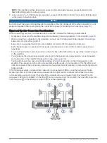
You must connect the REM terminal on the amplifier block to either the AMPLIFIER ON wire from the connected 
stereo or to a constant 12 Vdc power source using a switch. Connecting to the AMPLIFIER ON wire is 
recommended to avoid a popping sound when the stereo turns on or off.
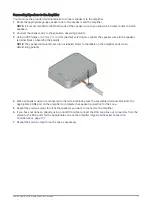
Route the 2 AWG (33.6 mm

2

) copper-coated aluminum wire (not included) to the amplifier and to a ground 

location on the boat.

Using a 5 mm (

7

/

32

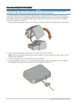
 in.) flat (slotted) screwdriver, connect the ground cable to the GND terminal on the power 

connection block.

Connect the other end of the ground wire to the ground location.
Route the 2 AWG (33.6 mm

2

) copper-coated aluminum wire (not included) to the amplifier and to the power 

source, and select an option:
• Install a properly rated in-line fuse on the power wire as close to the power source as possible.
• Identify or install a circuit breaker, as close to the power source as possible, for use with the amplifier 

power wire.

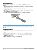
Using a 5 mm (

7

/

32

 in.) flat (slotted) screwdriver, connect the power (+) wire to the PWR terminal on the 

power connection block.

Route a 20 AWG (0.52 mm

2

) wire from the amplifier to the AMPLIFIER ON wire on the stereo or to a 12 Vdc 

power source through a switch.

Fusion Apollo Series Installation Instructions

9

Summary of Contents for Fusion Apollo MS-API2000

Page 1: ...ith Fusion DSP enabled marine audio equipment and may cause damage to third party speakers due to the amplifier power output When drilling or cutting always check what is on the opposite side of the s...

Page 2: ...m wire power 16 AWG 1 31 mm2 copper coated aluminum speaker wire speakers 14 AWG 2 08 mm2 copper coated aluminum speaker wire subwoofer NOTE You may need thicker wire for longer runs Speaker Wire Gaug...

Page 3: ...ach and detach the device from the mounting surface Mounting the device using the bracket requires clear space above the mounting location to allow for connecting the device to the bracket and install...

Page 4: ...sufficient clearance to install the device NOTE You must install the bracket with the release tab pointing up to properly secure the amplifier in the bracket 2 Using a 3 mm 1 8 in bit or a bit appropr...

Page 5: ...y above the mounting bracket 2 Place the device onto the bracket and pull down until the tab audibly clicks 3 Insert the wedge over the tab on the top of the mounting bracket it and push down to lock...

Page 6: ...g Bracket 1 Lift up to remove the wedge which unlocks the tab on the mounting bracket 2 Press the tab on the mounting bracket and lift up on the amplifier to disconnect it from the mount 6 Fusion Apol...

Page 7: ...mounting surface material drill the pilot holes NOTICE If you are mounting the device on fiberglass when drilling the pilot holes use a countersink bit to drill a clearance counterbore through only t...

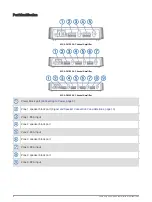
Page 8: ...wer block port Connecting to Power page 9 Zone 1 speaker block port Signal and Speaker Connection Considerations page 10 Zone 1 RCA input Zone 2 speaker block port Zone 2 RCA input Zone 3 speaker bloc...

Page 9: ...diameter larger gauge number wire becase of the increased material conductivity You must connect the REM terminal on the amplifier block to either the AMPLIFIER ON wire from the connected stereo or t...

Page 10: ...speaker load impedance and a 2 Ohm minimum speaker load impedance You can connect either a zone line out or a subwoofer line out from the stereo to any of the zone RCA inputs on the amplifier You shou...

Page 11: ...peaker terminal blocks are not labeled Refer to the labels on the amplifier ports when determining polarity 4 When all speaker wires are connected to the terminal block press the assembled terminal bl...

Page 12: ...bridge mode If needed you can purchase additional adapters from your Fusion dealer 1 Place the high power bridge adapter over an empty speaker terminal block and press until it clicks in place 2 Route...

Page 13: ...se 14 AWG 2 08 mm2 copper coated aluminum speaker wire for most installations You can use these tables to determine if you need to use a larger gauge of wire These tables account for terminal connecti...

Page 14: ...power terminal block to the amplifier NOTICE After you have completed all connections you must configure the DSP profile for the amplifier before playing music If the DSP profile is not set up you may...

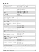
Page 15: ...put MS AP41200 1200 W MS AP61800 1800 W MS AP82400 2400 W Input sensitivity rated power output 4 Ohm 1 3 Vrms Signal to noise ratio rated power output 4 Ohm MS AP41200 67 1 dB MS AP61800 67 5 dB MS AP...

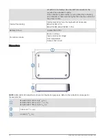
Page 16: ...ment necessary MS AP41200 85 A MS AP61800 MS AP82400 125 A Remote turn on Greater than 4 Vdc Protection circuits Reverse voltage Input under over voltage Over temperature Output short circuit Dimensio...

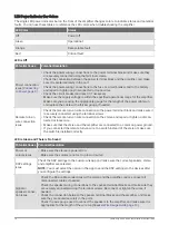
Page 17: ...a few simple troubleshooting steps to help diagnose the problem If the Fusion amplifier has been installed by a professional installation company you should contact the company so a technician can as...

Page 18: ...nected using the terminal screws Check the remote turn on wire connection to the stereo and repair or tighten a discon nected or loose wire Make sure that the stereo and the amplifier are connected to...

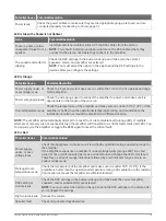
Page 19: ...tallation location or mount the amplifier in a different location NOTE The amplifier will automatically attempt to recover from a recoverable fault orange LED If multiple attempts of recovery are not...

Page 20: ...re are no cuts in the speaker wire jackets that may result in a short Internal amplifier or power supply fault Disconnect the amplifier from the power source for one minute then reconnect it and test...

Reviews: