background image

Mounting Considerations

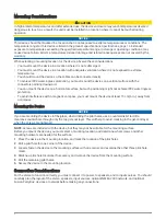
 CAUTION

In high ambient temperatures and after extended use, the device enclosure may reach temperatures deemed 
dangerous to touch. As a result, the unit must be installed in a location where it cannot be touched during 
operation.

NOTICE

This device should be mounted in a location that is not exposed to extreme temperatures or conditions. The 
temperature range for this device is listed in the product specifications 

Specifications, page 16

. Extended 

exposure to temperatures exceeding the specified temperature range, in storage or operating conditions, may 
cause device failure. Extreme-temperature-induced damage and related consequences are not covered by the 
warranty.

When selecting a mounting location for the device, observe these considerations.
• You must mount the device in a location where it is not submerged.
• You must mount the device in a location with adequate ventilation where it is not exposed to extreme 

temperatures.

• You should mount the device so the cables can be connected easily.
• To achieve IPX2 water ingress protection, you must mount the device on a vertical surface with the 

connectors pointing downward.

• You can mount the device on a horizontal surface, but such positioning might not achieve IPX2 water ingress 

protection.

• To avoid interference with a magnetic compass, you must mount the device at least 15 cm (6 in.) away from 

a compass.

Mounting the Device

NOTICE

If you are mounting the device in fiberglass, when drilling the pilot holes, use a countersink bit to drill a 
clearance counterbore through only the top gel-coat layer. This will help to avoid cracking in the gel-coat layer 
when the screws are tightened.

NOTE: Screws are included with the device, but they may not be suitable for the mounting surface.
Before you mount the device, you must select a mounting location, and determine what screws and other 
mounting hardware are needed for the surface.
Place the device in the mounting location, and mark the location of the pilot holes.
Drill a pilot hole for one corner of the device.
Loosely fasten the device to the mounting surface with one corner, and examine the other three pilot-hole 

marks.

Mark new pilot-hole locations if necessary, and remove the device from the mounting surface.
Drill the remaining pilot holes.
Secure the device to the mounting location.

Connection Considerations

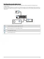
For the stereo to function correctly, you must connect it to power, to speakers, and to input sources. You should 
carefully plan the layout of the stereo, speakers, input sources, optional NMEA 2000 network, and optional 
Fusion PartyBus

 devices or network before making any connections.

2

Summary of Contents for FUSION APOLLO MS-WB675

Page 1: ...a dust mask when drilling cutting or sanding NOTICE When drilling or cutting always check what is on the opposite side of the surface to avoid damaging the vessel Do not use the stereo as a template...

Page 2: ...ing might not achieve IPX2 water ingress protection To avoid interference with a magnetic compass you must mount the device at least 15 cm 6 in away from a compass Mounting the Device NOTICE If you ar...

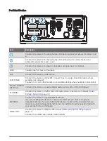
Page 3: ...ive DAB stations where available not included DIGITAL AUDIO IN OPTICAL Connects the stereo to an optical digital audio source such as TV or DVD player ETHERNET Connects the stereo to another Fusion Pa...

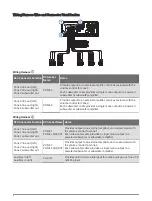
Page 4: ...to a powered subwoofer or subwoofer amplifier Wiring Harness RCA Connector Function RCA Label Name Notes Zone 1 line out left Zone 1 line out right Zone 1 subwoofer out ZONE 1 ZONE 1 SUB OUT Provides...

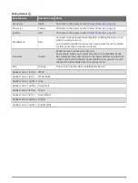
Page 5: ...signal wire to function correctly Telemute Brown Activates when connected to ground For example when you connect this wire to a compatible hands free mobile kit the audio mutes or the input switches...

Page 6: ...turn the stereo on and off automatically when you turn the vessel on and off or when you activate the switch Using this wire to turn the stereo on and off behaves in the same way as using the power bu...

Page 7: ...s switch is needed only if a circuit breaker is not available or if it provides a more convenient method of cutting power to the stereo Black wire Ground 15 A fuse not included This fuse is required i...

Page 8: ...1 A fuse not included You must install this fuse on the red wire before you connect the red wire to the ignition or ACC switch Ignition or ACC switch Connecting the red wire to this switch allows the...

Page 9: ...zones individually For example you could make the audio quieter in the cabin and louder on deck Up to two pairs of speakers can be connected per channel of each zone in parallel One zone can support...

Page 10: ...onnected to a zone line out A connected amplifier must use the same ground as the stereo for this signal wire to function correctly Powered amplifier connected to the zone 2 line out Zone 2 line out a...

Page 11: ...er with a built in GPS antenna a wind instrument or a water speed sensor it can be configured to automatically adjust the volume according to the engine RPM the speed over ground the wind speed or the...

Page 12: ...controls whether they are grouped or not to adjust the volume of the available speaker zones for any stereo on the network Wired Networking Considerations When you are planning your network installat...

Page 13: ...etwork setting changes are needed when connecting multiple Fusion PartyBus devices using a switch but if you are using a router you may need to configure it to be a DHCP server See your router instruc...

Page 14: ...ecessary All stereos should use their default configuration DHCP CLIENT 7 Test the network by selecting GROUPS to view a list of devices connected to the on the network and select an option If any dev...

Page 15: ...to the network using an Ethernet cable Verify that only one device either a stereo or a router is configured as a DHCP server Change the channel on your router or wireless access point to test for and...

Page 16: ...ncies protocols Bluetooth 2 4 GHz 12 dBm nominal ANT 2 4 GHz 11 77 dBm nominal Compass safe distance 15 cm 6 in On board Class D amplifier Output music power per channel 4 x 70 W max 2 ohm Total outpu...

Page 17: ...Drawings Side Dimensions 107 mm 4 21 in 55 mm 2 17 in 130 mm 5 10 in Top Dimensions 130 mm 5 10 in 130 mm 5 10 in Software Updates Go to support garmin com to find software updates and information fo...

Page 18: ...mission of Garmin Apple is a trademark of Apple Inc registered in the USA and other countries App Store SM is a service mark of Apple Inc registered in the USA and other countries Android and Google P...

Reviews: