background image

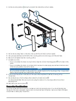
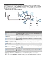
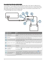
Route all wires to the stereo wiring harness, the ignition or ACC switch, the circuit breaker, and the power 

source as necessary.
Do not connect the wiring harness to the stereo until after you have made all of the bare wire connections.

Install all of the necessary fuses on the red and yellow wires.
Connect the wiring harness to the stereo.
When you turn on the ignition switch, the stereo turns on along with other accessory electronics. When you turn 
off the ignition switch, the stereo enters a low-power standby mode.
NOTE: When you are not using the vehicle for an extended period of time, you should remove power to the 
stereo using the circuit breaker or other manual switch on the yellow wire to avoid draining the battery.

Enabling Standby Mode

By default, when you turn off the ignition (when connected) or hold  , the device turns off, and you must press 

 to turn it on again.

You can set the stereo to enter a standby mode when you turn off the ignition (when connected) or hold  . 
When you turn on the ignition, it takes less time to turn on than with standby mode disabled.
You can enable standby mode on the device so you can turn it on using another device on the network instead 
of pressing  .
NOTE: When the device is off, it continues to draw approximately 80 mA from the battery. When you enable 
standby mode, the device draws more current because it is listening for a power-on signal over the network. 
When the device is off with standby mode enabled, it continues to draw approximately 110 mA. Standby mode 
does not apply when the device is configured to run as an EmpirBus

 Web Display Unit (WDU). Networking 

remains active for switching functionality even when the display is turned off using the power button.

Select 

 > SETTINGS > POWER OPTIONS > STANDBY MODE.

The stereo now enters standby mode when you hold   or turn off the ignition.

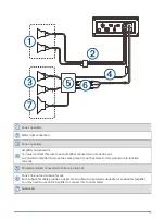
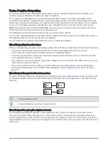
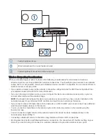
Speaker Zones

You can group speakers in one area into a speaker zone. This enables you to control the audio level of the 
zones individually. For example, you could make the audio quieter in the cabin and louder on deck.
Up to two speakers can be connected per channel (left and right) of each zone, in parallel. A zone can support 
no more than four speakers using the on-board amplifier.
Zones 1 and 2 are powered by the on-board amplifier. To use the RCA line outputs and the RCA subwoofer 
outputs for zones 1 and 2, you must connect external amplifiers.
Zones 3 and 4 are available as line-level outputs only. To use the RCA line outputs and the RCA subwoofer 
outputs for zones 3 and 4, you must connect external amplifiers.
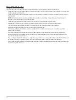
You can set the balance, volume limit, tone, subwoofer frequency, and name for each zone, and configure other 
zone-specific settings.

11

Summary of Contents for Fusion APOLLO RV-RA770

Page 1: ...void possible personal injury always wear safety goggles ear protection and a dust mask when drilling cutting or sanding NOTICE When drilling or cutting always check what is on the opposite side of th...

Page 2: ...the Stereo NOTICE Do not use the stereo as a template when drilling the mounting holes because this may damage the display and void the warranty You must only use the included template to correctly dr...

Page 3: ...ound the cutout NOTICE Do not install the included mounting gasket if you applied sealant to the mounting surface Using sealant and the mounting gasket may reduce water resistance 8 If you will not ha...

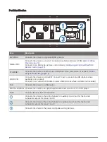
Page 4: ...to a SiriusXM Connect Tuner to receive SiriusXM stations where available not included Connects to a Fusion DAB module to receive DAB stations where available not included USB Connects the stereo to a...

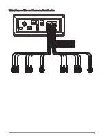
Page 5: ...Wiring Harness Wire and Connector Identification 5...

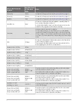
Page 6: ...r zone 1 left White Speaker zone 1 left White black Speaker zone 1 right Gray Speaker zone 1 right Gray black Speaker zone 2 left Green Speaker zone 2 left Green black Speaker zone 2 right Purple Spea...

Page 7: ...he stereo when storing the vehicle If it is necessary to extend this wire use 14 AWG 2 08 mm2 wire For extensions longer than 1 m 3 ft use 12 AWG 3 31 mm wire Red wire This wire can be connected to th...

Page 8: ...hould connect this wire to the yellow wire so that it does not act as a physical standby switch 1 A fuse not included You must install this fuse on the red wire before you connect the red wire to the...

Page 9: ...ual switch is closed the stereo is always on You can use the power button on the stereo or a connected device or remote control to place the stereo in a low power standby mode if needed NOTE When you...

Page 10: ...n or ACC switch Red wire You must connect this wire to the ignition or ACC switch before you connect it to the same power source as the yellow wire 1 A fuse not included You must install this fuse on...

Page 11: ...draw approximately 80 mA from the battery When you enable standby mode the device draws more current because it is listening for a power on signal over the network When the device is off with standby...

Page 12: ...ne 2 on the stereo using a line out You can connect an amplifier and subwoofer to any or all of the available zones on the stereo NOTE You can connect speakers to the speaker wires for the internal st...

Page 13: ...ected amplifier must use the same ground as the stereo for this signal wire to function correctly Powered amplifier connected to the zone 2 line out Zone 2 line out and subwoofer out Each subwoofer ca...

Page 14: ...System Wiring Diagram The Apollo RV RA770 device uses NMEA 2000 cables and hardware to connect with other devices using a Garmin Controller Area Network Garmin CAN 14...

Page 15: ...ional configuration is needed 1 Select SETTINGS POWER OPTIONS 2 Select an option If you connected both your stereo and your optional wired remote to a Garmin CAN bus make sure the NRX POWER option is...

Page 16: ...using standard Cat5e or Cat6 network cables with RJ45 connectors You can use one network cable to directly connect two compatible devices You must use wired network switches and wired or wireless net...

Page 17: ...point so you can connect other devices within wireless range NOTE You should not configure this device as a wireless access point if you have a router installed on the network because it may introduce...

Page 18: ...Wireless Access Point Example Fusion PartyBus stereo Fusion PartyBus zone stereo Smartphone using the Fusion Link app Wireless Network Example with a Wired Switch or Router 18...

Page 19: ...Fusion PartyBus zone stereo Smartphone using the Fusion Link app Wireless Network Example with a Wireless Router or Access Point Fusion PartyBus stereo Wireless network router or wireless access point...

Page 20: ...Bus Device as a Wireless Access Point page 21 Configuring a stereo as a wireless access point makes that stereo the DHCP server and all of the other stereos on the network should use their default con...

Page 21: ...configuration instructions see the owner s manual 1 Select SETTINGS NETWORK WI FI ACCESS POINT 2 Select USE DEFAULTS and wait for the device to save the network settings NOTE After the default settin...

Page 22: ...correct interference You may experience wireless interference if there are many nearby wireless access points Disconnect Bluetooth devices to test for and correct interference Connecting a Bluetooth...

Page 23: ...WDU disabled 10 mA Fuse 15 A mini blade type NMEA 2000 LEN 9 Vdc 1 50 mA Bluetooth wireless range Up to 10 m 30 ft ANT wireless range Up to 3 m 10 ft Wireless frequencies protocols Wi Fi 2 4 GHz 15 dB...

Page 24: ...range 522 to 1620 kHz 530 to 1710 kHz 522 to 1620 kHz AM frequency step 9 kHz 10 kHz 9 kHz Stereo Dimension Drawings Side Dimensions 20 4 mm 0 8 in 99 mm 3 9 in 50 mm 1 97 in Top Dimensions 164 mm 6...

Page 25: ...tore SM is a service mark of Apple Inc registered in the USA and other countries Android and Google Play are a trademarks of Google Inc BLUETOOTH word mark and logos are owned by the Bluetooth SIG Inc...

Page 26: ...2021 Garmin Ltd or its subsidiaries support garmin com...

Reviews: