Garmin G1000 Pilot’s Guide for the Diamond DA62
190-01895-00 Rev. A
2
SYSTEM OVERVIEW
SY
STEM
O
VER
VIEW
FLIGHT
INSTRUMENTS
EIS
AUDIO P
ANEL
& CNS
FLIGHT
MANA
GEMENT
HAZARD
AV
OID
ANCE
AFCS
ADDITIONAL FEA
TURES
APPENDICES
INDEX
1.1 LINE REPLACEABLE UNITS
•
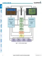
GDU 1040/1045
(2) – A GDU 1040 is configured as the Primary Flight Display (PFD) and a GDU 1045 as
the Multi Function Display (MFD). Both displays feature 10.4-inch LCD screens with 1024 x 768 resolution.
The displays communicate with each other through a High-speed Data Bus (HSDB) Ethernet connection. Each
display is also paired with an Ethernet connection to an IAU.
•
GMA 1347
– The Audio Panel integrates navigation/communication radio (NAV/COM) digital audio, intercom,
and marker beacon controls, and is installed between the displays. This unit also provides manual control
of display Reversionary Mode (red
DISPLAY BACKUP
button; see Section 1.4, System Operation) and
communicates with both IAUs using an RS-232 digital interface.
•
GIA 63W
(2) – The Integrated Avionics Units (IAU) function as the main communications hub, linking all LRUs
with the PFD. Each GIA 63W contains a GPS SBAS receiver, VHF COM/NAV/GS receivers, a flight director (FD;
if Garmin AFCS is installed), and system integration microprocessors. Each GIA 63W is paired with the on-side
display via an HSDB connection. The IAUs are not paired together and do not communicate with each other
directly.
NOTE:
Refer to the Airplane Flight Manual (AFM) to determine whether SBAS functionality is approved.
•
GDC 74A
– The Air Data Computer (ADC) processes data from the pitot/static system and outside air temperature
(OAT) sensor. The ADC provides pressure altitude, airspeed, vertical speed, and OAT information to the G1000
System, and it communicates with the primary IAU, displays, and AHRS using an ARINC 429 digital interface.
•
GEA 71
– The Engine Airframe Unit receives and processes signals from the engine and airframe sensors. This
unit communicates with both IAUs using an RS-485 digital interface.
•
GTX 33 or GTX 33 with Extended Squitter
– The GTX 33 solid-state Transponder provides Modes A, C, and
S capability. The GTX 33 with Extended Squitter will also provide 1090 MHz Extended Squitter (1090ES)
transmit capability. The transponder communicates with both IAUs through
an RS-232 digital interface.
•
GRS 77
(2) – The Attitude and Heading Reference System (AHRS) provides aircraft attitude and heading
information via ARINC 429 to both the PFD and the primary IAU. The AHRS contains advanced sensors
(including accelerometers and rate sensors) and interfaces with the Magnetometer to obtain magnetic field
information, with the ADC to obtain air data, and with both IAUs to obtain GPS information. AHRS operation
is discussed in Section 1.4, System Operation.
•
GMU 44
– The Magnetometer measures local magnetic field and sends data to the AHRS for processing to
determine aircraft magnetic heading. This unit receives power directly from the AHRS and communicates with
it via an RS-485 digital interface.
•
GDL 69/69A
– The Data Link Satellite Radio Receiver provides real-time weather information to MFD maps
and the PFD Inset Map. The GDL 69A model is also capable of providing digital audio entertainment. The
Data Link Receiver communicates with the MFD via an HSDB connection. A subscription to XM Satellite Radio
Service is required to enable Data Link Receiver capability.
•
GSA 80, GSA 81
and
GSM 86
– The GSA servos are used for the automatic control of pitch, pitch trim, roll and
yaw. These units interface with each IAU.
The GSM 86 servo mounts are responsible for transferring the output torque of the servo actuators to the
mechanical flight-control surface linkages (not displayed in Figure 1-1).


